Sensor pixel and touch panel thereof

一种触控面板、像素的技术,应用在仪器、电数字数据处理、数据处理的输入/输出过程等方向,能够解决错误定位等问题

Inactive Publication Date: 2009-08-19
HIMAX TECH LTD
View PDF0 Cites 14 Cited by
  • Summary
  • Abstract
  • Description
  • Claims
  • Application Information

AI Technical Summary

Problems solved by technology

However, optical touch panels are very sensitive to tiny objects or external disturbances, which can easily lead to wrong positioning

Method used


Image

  • Sensor pixel and touch panel thereof
  • Sensor pixel and touch panel thereof
  • Sensor pixel and touch panel thereof

Examples


Embodiment Construction

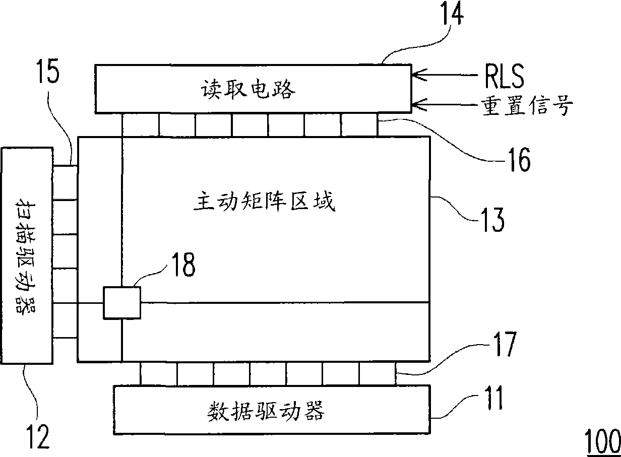
[0055] figure 1 It is a block diagram of a touch panel according to an embodiment of the present invention. Please refer to figure 1 The touch panel 100 includes a scan driver 12, a data driver 11, a read circuit 14 and an active matrix area 13, wherein the touch panel 100 has m scan lines 15 and n read lines 16. A plurality of display pixels (not shown in the figure 1 ) And multiple sensing pixels 18. The scan driver 12 transmits scan driving signals to the display pixels through the scan lines 15 and the data driver 11 transmits data driving signals to the display pixels through the data lines 17 to display image frames.

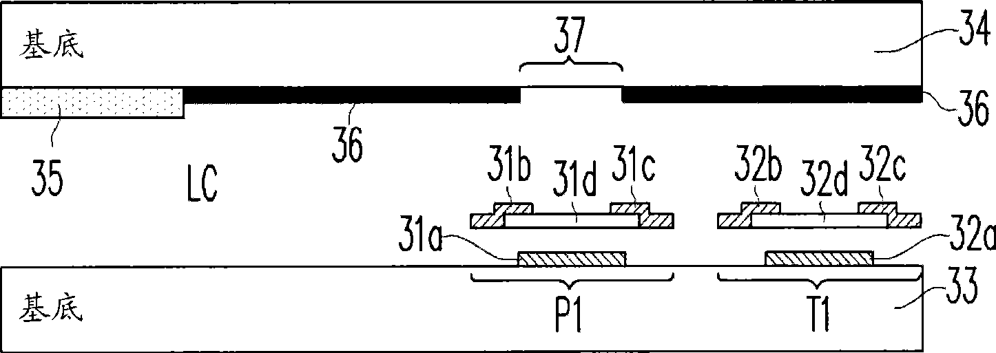
[0056] figure 2 It is a circuit diagram of a display pixel and a sensing pixel coupled together in an embodiment of the present invention. Please refer to figure 2 The display pixel 19 includes a transistor T0, a storage capacitor Cst, and a liquid crystal layer, where the liquid crystal layer is represented by a liquid crystal capacitor Clc. The gate a...


PUM


Abstract

A sensor pixel and a touch panel using the same are provided herein, wherein the touch panel has m scan lines and n readout lines. The sensor pixel includes a sensing capacitor, a readout transistor, a reset transistor, a base transistor, and a photo transistor. The photo transistor included in the sensor pixel produces a photo leakage current when it is exposed to a light. The light obstruction characteristic of the photo transistor is utilized to detect the locations of the touched sensor pixels. By proper timing control, the present invention not only can be applied to the multi-finger detection, but also is easy to be implemented.

Description

Technical field [0001] The present invention relates to a sensing pixel of a touch panel, and more particularly to a sensing pixel having a phototransistor to detect a touched position. Background technique [0002] With the vigorous development of electronic technology and the popularization of wireless communications and networks, portable devices with the advantages of lightness, thinness and shortness have gradually become a new generation of data access platforms. However, not all devices use common input / output (I / O) interfaces, such as keyboards or mice. Therefore, the touch panel is often used as a human-machine interface between humans and smart devices to perform control. [0003] Generally speaking, a resistive touch panel is composed of two conductive layers separated by a small space. When the user presses the touch panel, the two conductive layers will be connected to a certain point, so a voltage change will occur at this point. After an analog signal with a voltag...

Claims


Application Information

Patent Timeline
Patent Type & Authority Applications(China)
IPC IPC(8): G06F3/041
CPCG06F3/042G06F3/0412
Inventor 庄凯岚
Owner HIMAX TECH LTD
Why Eureka
Try Eureka