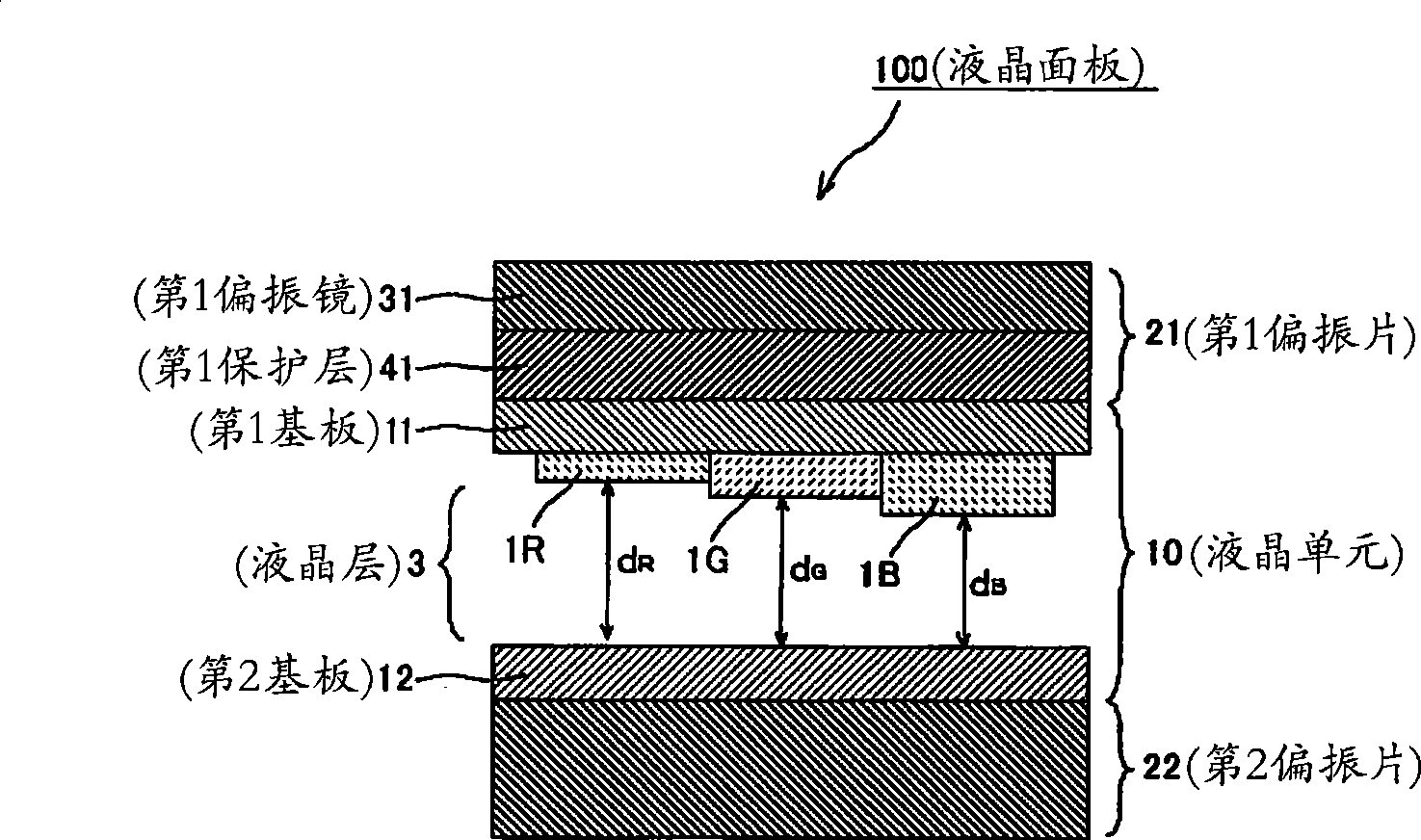
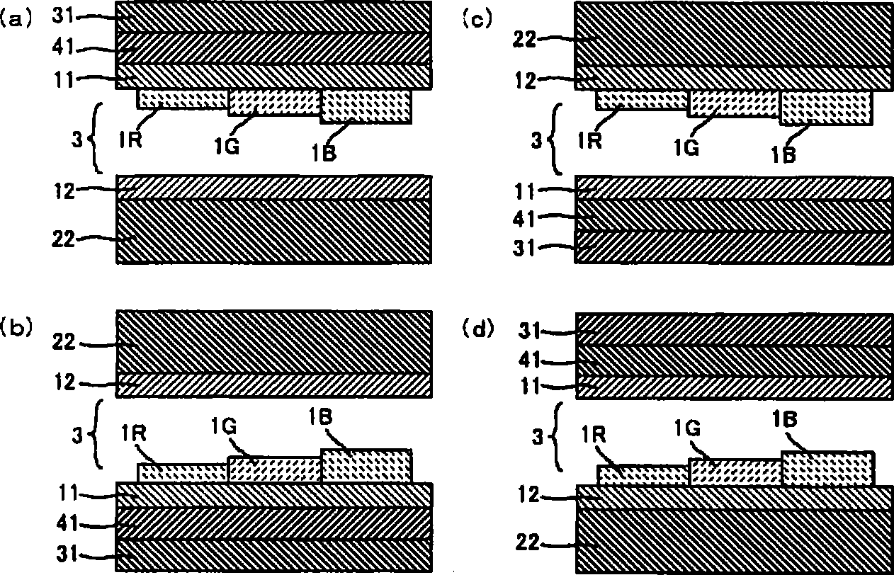
Liquid crystal panel comprising liquid crystal cell having multigap structure, and liquid crystal display device
A technology of liquid crystal panels and liquid crystal units, applied in optical elements, polarizing elements, optics, etc., can solve problems such as large chromatic aberrations, and achieve the effect of reducing chromatic aberrations
- Summary
- Abstract
- Description
- Claims
- Application Information
AI Technical Summary
Problems solved by technology
Method used
Image
Examples
Embodiment
[0116] The present invention is further illustrated using the following examples and comparative examples. In addition, this invention is not limited only to a following Example.
[0117] (1) The measurement method of the single transmittance of the polarizer:
[0118] The Y value after the visibility correction was measured using a spectrophotometer [manufactured by Murakami Color Technology Laboratory Co., Ltd., product name "DOT-3"] with a 2-degree field of view (C light source) according to JIS Z 8701-1982.
[0119] (2) The measuring method of the degree of polarization of the polarizer:
[0120] The parallel transmittance (H 0 ) and orthogonal transmittance (H 90 ), using the formula: degree of polarization (%)={(H 0 -H 90 ) / (H 0 +H 90 )} 1 / 2 ×100 obtained. The above parallel transmittance (H 0 ) is a value of the transmittance of a parallel laminated polarizing plate produced by superimposing two identical polarizing plates so that their absorption axes are par...
reference example 1
[0128] Production of liquid crystal unit
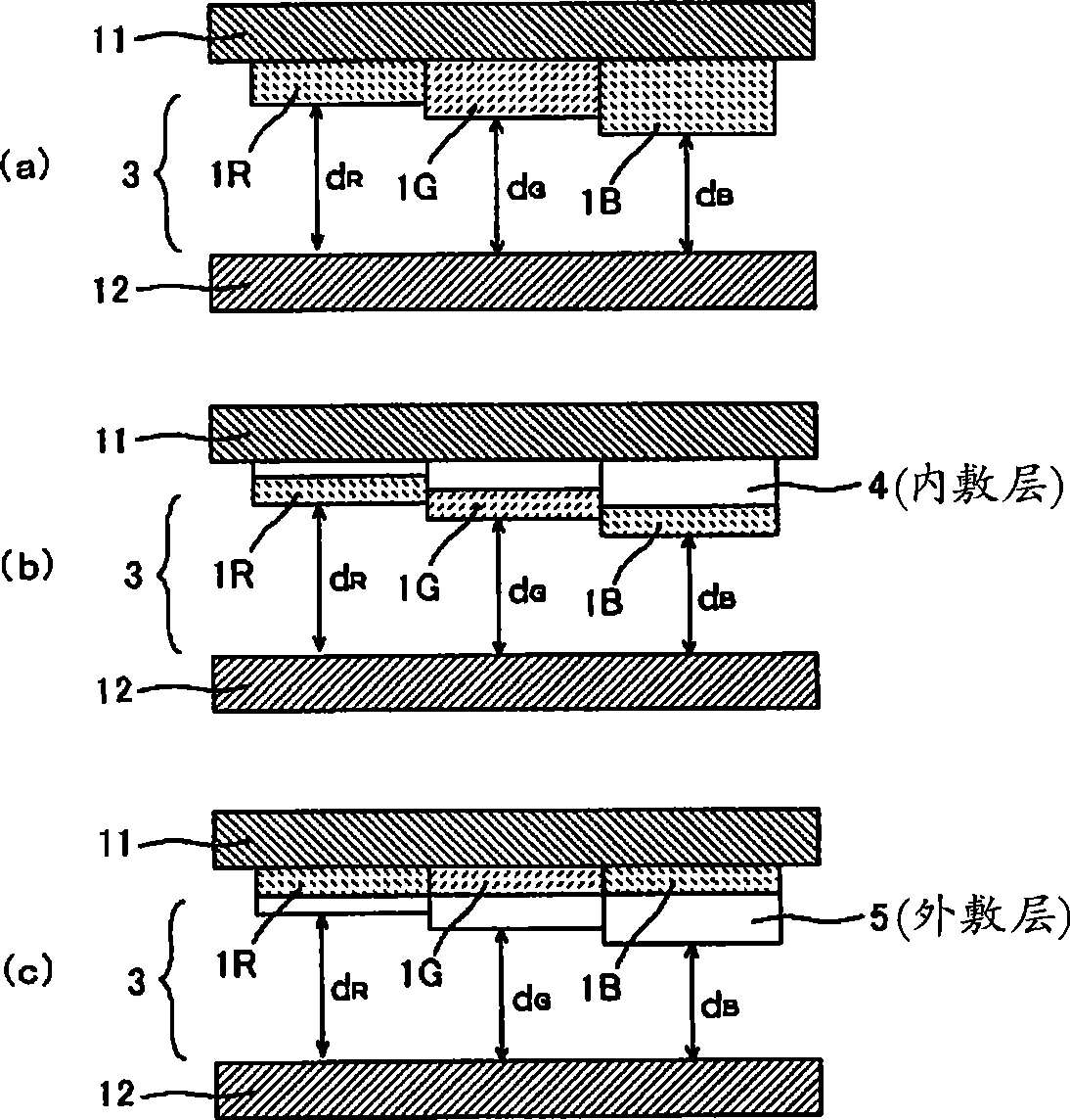
[0129] A colored resin solution in which a pigment is dispersed is applied on a glass substrate on which a black matrix is formed, and is prebaked and dried to form a colored resin layer. Next, a positive resist (positive resist) is applied on this colored resin layer, exposure is performed using a photomask, development of the positive resist and etching of the colored resin layer are performed using a developer. After that, the positive resist is stripped. In order to form red, green, and blue color filters, this operation was repeated three times, and the thickness of the colored resin layer (color filter) of each color was changed, and the color filter board|substrate was produced.
[0130] Next, thin film transistors, scanning lines, signal lines, and pixel electrodes are formed on another glass substrate to produce an active matrix substrate. An oriented film was formed on the two substrates, and the surface of the film wa...
reference example 2
[0134] Production of the first polarizer
[0135] A polymer film (trade name "VF-PS#7500" manufactured by Kuraray Co., Ltd.) mainly composed of a polyvinyl alcohol-based resin with a thickness of 75 μm was immersed in an aqueous solution containing iodine and potassium iodide (iodine Concentration = 0.03% by weight), and tension was applied to the film in the longitudinal direction, and stretched so that the final stretch ratio was 6.2 times the original length to produce a polarizer (a). The polarizer (a) has a thickness of 25 μm, a degree of polarization P=99%, and a single transmittance T=43.5%.
[0136] Next, a norbornene-based polymer film [optes( Co., Ltd. (Optes Inc.) product name "ZEONOR ZF14"] was stretched to 1.2 times to produce a retardation film (a). The refractive index ellipsoid of the retardation film (a) satisfies the relationship of nx>ny>nz,
[0137] Thickness 32μm,
[0138] T[550]=90%,
[0139] Re[550]=60nm,
[0140] Rth[550]=72nm,
[0141] Nz coef...
PUM
| Property | Measurement | Unit |
|---|---|---|
| thickness | aaaaa | aaaaa |
| thickness | aaaaa | aaaaa |
| thickness | aaaaa | aaaaa |
Abstract
Description
Claims
Application Information
 - R&D
- Intellectual Property
- Life Sciences
- Materials
- Tech Scout
- Unparalleled Data Quality
- Higher Quality Content
- 60% Fewer Hallucinations
Browse by: Latest US Patents, China's latest patents, Technical Efficacy Thesaurus, Application Domain, Technology Topic, Popular Technical Reports.
© 2025 PatSnap. All rights reserved.Legal|Privacy policy|Modern Slavery Act Transparency Statement|Sitemap|About US| Contact US: help@patsnap.com


