
Yoke for universal joint

A technology for universal joints and fastening parts, applied to rigid shaft couplings, elastic couplings, mechanical equipment, etc., can solve the problem of inability to completely prevent the bending of bolts 109, the complex shape of fastening parts 107, and fatigue resistance. (Decrease in durability and other issues, achieve the effect of reducing manufacturing cost, preventing bolt bending, and suppressing manufacturing cost

Inactive Publication Date: 2009-08-05
KOYO MASCH IND CO LTD
View PDF1 Cites 7 Cited by
  • Summary
  • Abstract
  • Description
  • Claims
  • Application Information

AI Technical Summary

Problems solved by technology

[0009] However, in the above-mentioned second yoke 105, when the pair of fastening portions 107 are fastened by the bolts 109, as Figure 11 As shown, there will be the following problem: the front end sides of the fastening part 107 are deformed in a manner approaching each other, the bolt 109 is bent, and the bolt 109 is subjected to not only tensile stress but also bending stress, so the resistance of the bolt 109 Reduced fatigue strength (durability)
[0014] However, in the yoke 120 disclosed in the above-mentioned conventional Japanese Patent Application Laid-Open No. 7-317793, as described above, when the bolt 109 and the nut 121 are used for fastening, although the abutment of the abutting portion 107d prevents the fastening The front end side of the part 107 is deformed and approached, but because the fastening position of the bolt 109 and the nut 121 is separated from the contact position of the two abutting parts 107d, as Figure 13 As shown, the roots of the fastening part 107 on the side of the insertion part 106 are deformed and approach each other. Although not shown in the figure, since the central part of the fastening part 107 is deformed and deflected, the bolt 109 cannot be completely prevented from bending.
[0015] Therefore, even the above-mentioned yoke 120 is the same as the above-mentioned second yoke 105, the bolt 109 is subjected to not only tensile stress but also bending stress due to deformation, and the durability of the bolt 109 is reduced.
[0016] In addition, when forming the above-mentioned abutting portion 107d, there is also the problem that the shape of the above-mentioned fastening portion 107 becomes complicated, the forming becomes difficult, the forming process increases, and the shape of the mold for forming becomes complicated, and because the forming becomes difficult, the forming process increases. , the shape of the mold used for forming becomes complicated, which leads to the problem of increased manufacturing cost

Method used


Image

  • Yoke for universal joint
  • Yoke for universal joint
  • Yoke for universal joint

Examples


Embodiment Construction

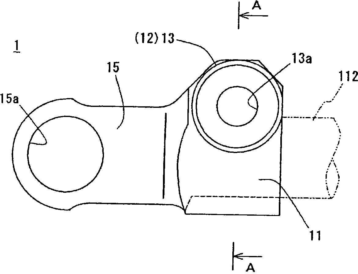
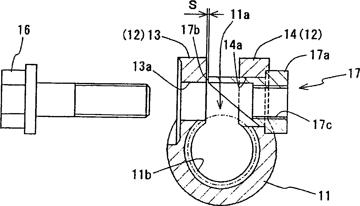
[0050] Hereinafter, specific embodiments of the present invention will be described with reference to the drawings. in, figure 1 It is a front view showing a schematic structure of a yoke for a universal joint according to an embodiment of the present invention, figure 2 It is a rear view showing a schematic structure of a yoke for a universal joint according to this embodiment, image 3 for along figure 1 A cross-sectional view in the direction of arrow A-A, Figure 4 It is a side view showing the schematic structure of the nut in this embodiment. Also, in the following description, Figure 1 ~ Figure 4 The universal joint shown in this example uses yoke 1 that replaces Figure 9 ~ Figure 11 In the case of the second yoke 105 shown, descriptions other than the yoke 1 will be given the same reference numerals as those described above, and detailed description will be omitted.

[0051] Such as Figure 1 ~ Figure 4 As shown, the yoke (second yoke) 1 for a universal joi...


PUM


Abstract

A yoke for a universal joint, where deformation of a set of a fastening section and a bolt is prevented, increasing durability of the bolt. The yoke (1) for a universal joint has an insertion section (11) formed in a tubular shape with an opening in the direction of axis of a rotating shaft and into which one end of the rotating shaft is inserted, a first fastening section (13) and a second fastening section (14) as a pair of fastening sections (12) extended from the insertion section (11) so as to face each other with an opening of the insertion section (11) held in between, and a set of a bolt (16) and a nut (17) for tightening the pair of fastening sections (12) from both sides. When the pair of fastening sections (12) is fastened together, the rotation shaft inserted in the insertion section (11) is held and fixed. The bolt (16) is inserted in a through-hole (13a) of the first fastening section (13). The nut (17) is fitted in an engageable manner in a through-hole (14a) of the second fastening section (14), and that portion of the end face of the nut (17) which faces the first fastening section (13) is formed extended toward the first fastening section (13) such that a gap (S) between the extended portion and the first fastening section (13) has a predetermined width.

Description

technical field [0001] The present invention relates to a yoke for a universal joint connecting one end side of a rotating shaft. Background technique [0002] A universal joint 100 connects 2 shafts whose axes cross at an angle, and is used to transmit torque from one shaft to the other, for example, as Figure 9 As shown, it is composed of a cross shaft 101 whose axes are perpendicular to each other and two yokes 102, 105 (first yoke 102 and second yoke 105), wherein the yokes 102, 105 are respectively connected to two shafts constituting the cross shaft 101. The ends are provided at the center of the axis so as to be able to swing freely, and are respectively connected to one end sides of the rotation shafts 111 and 112 . [0003] Moreover, such a universal joint 100 is provided, for example, on a steering device of an automobile, and the steering device is configured to transmit the torque of a steering shaft 111 rotated by an operation of a steering wheel (handle) to th...

Claims


Application Information

Patent Timeline
Patent Type & Authority Applications(China)
IPC IPC(8): F16D3/38
CPCF16D1/0864F16D3/387
Inventor 柿本和秀井上圣准小山刚司
Owner KOYO MASCH IND CO LTD
Learn More