Focal spot size measurement with a movable edge located in a beam-shaping device
A beam shaping and focal spot technology, applied in the field of X-ray imaging, can solve the problems of complex model manufacturing and complex surface structure, and achieve the effect of high edge response magnification
- Summary
- Abstract
- Description
- Claims
- Application Information
AI Technical Summary
Problems solved by technology
Method used
Image

Examples
Embodiment Construction
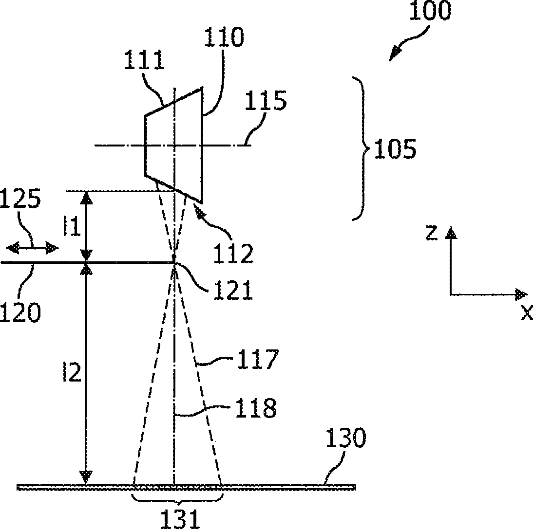
[0056] Figure 1a A schematic diagram of a medical X-ray imaging apparatus 100 is shown. The medical X-ray imaging device 100 comprises an X-ray tube 105 with an anode 110 . The anode 110 is rotatably supported within a rotating shaft 115 . An electron beam is emitted from an electron source (not shown), whereby the electrons impinge on the surface 111 of the anode within a focal spot 112 . The focal spot 112 has a spatial magnification due to the limited focusing of the electron beam.
[0057] X-ray beam 117 originates from focal spot 112 and projects along optical axis 118 . During normal operation of the medical X-ray imaging apparatus 100, the X-ray beam 117 at least partially penetrates an object under examination (not shown), and the flat panel X-ray detector 130 receives an image representing a two-dimensional X-ray attenuation distribution. In this context, it is evident that the larger the size of the focal spot 112 is, the larger the unsharpness of the entire imag...
PUM
 Abstract
Description
Claims
Application Information
 - Generate Ideas
- Intellectual Property
- Life Sciences
- Materials
- Tech Scout
- Unparalleled Data Quality
- Higher Quality Content
- 60% Fewer Hallucinations
Browse by: Latest US Patents, China's latest patents, Technical Efficacy Thesaurus, Application Domain, Technology Topic, Popular Technical Reports.
© 2025 PatSnap. All rights reserved.Legal|Privacy policy|Modern Slavery Act Transparency Statement|Sitemap|About US| Contact US: help@patsnap.com