
Electronic power variation, speed variation wind power generator

A technology for wind power generators and generators, applied in wind power generation, control of generators, electrical components, etc., can solve problems such as short connection time, reduced blade life, increased blade load, etc., to save capital investment and improve wind energy utilization The effect of high and long online time

Inactive Publication Date: 2009-07-29
刘旭东
View PDF0 Cites 2 Cited by
  • Summary
  • Abstract
  • Description
  • Claims
  • Application Information

AI Technical Summary

Problems solved by technology

Most of the equipment produced in the early stage was fixed propeller, constant speed gearbox, and constant power generator. This product cannot adjust the speed when the wind speed is variable. When the wind is strong, the wind generator will overspeed, causing the blades to break and the generator to be damaged. Burned out; later products adopt blade tip reverse speed regulation, and its structure is complicated, which increases blade load and reduces blade life; current wind turbines use pitch to adjust speed, but still use constant speed increase Although the gearbox and constant power generator are better than the aforementioned wind generators, they are not suitable for strong wind areas with variable wind speeds. Although the direct drive wind generators do not have gearboxes, they also use variable pitch speed regulation. However, the generator adopts a low-speed constant power and constant voltage design, and is not suitable for strong wind areas with variable wind speeds.
Therefore, the existing wind turbines have the disadvantages that they cannot be connected to the grid at low speeds, cannot generate electricity at high speeds, and are only connected to the grid at medium speeds, but the time to connect to the grid is short, and they cannot make full use of wind energy.

Method used


Image

  • Electronic power variation, speed variation wind power generator
  • Electronic power variation, speed variation wind power generator
  • Electronic power variation, speed variation wind power generator

Examples


Embodiment Construction

[0011] The present invention will be described in detail below in conjunction with the accompanying drawings and embodiments.

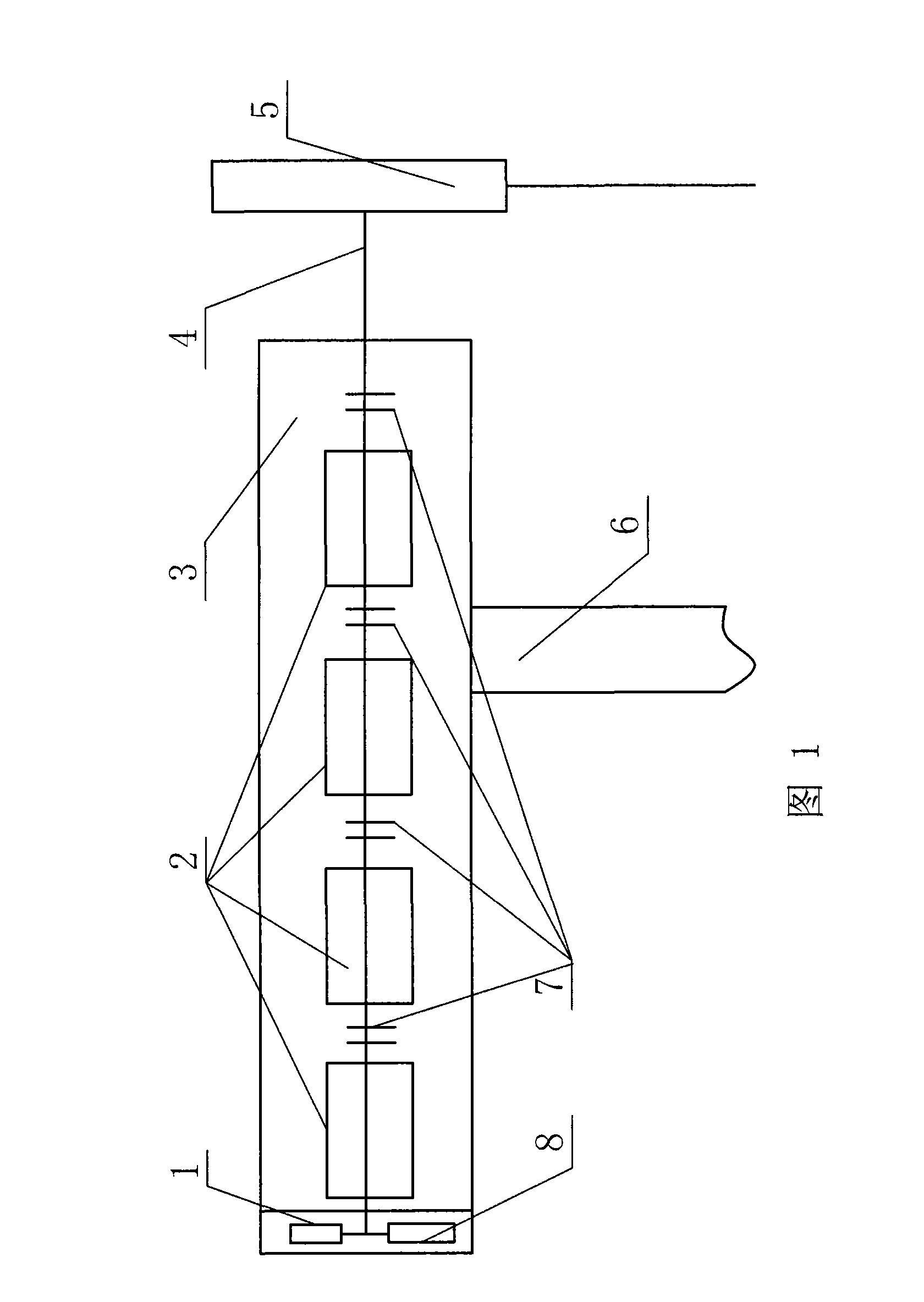
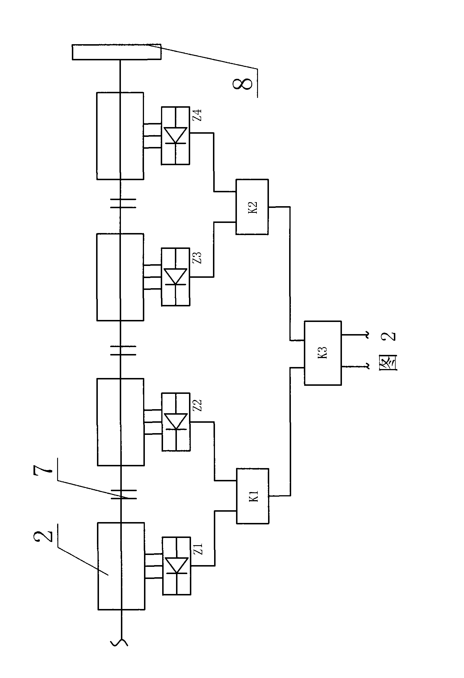
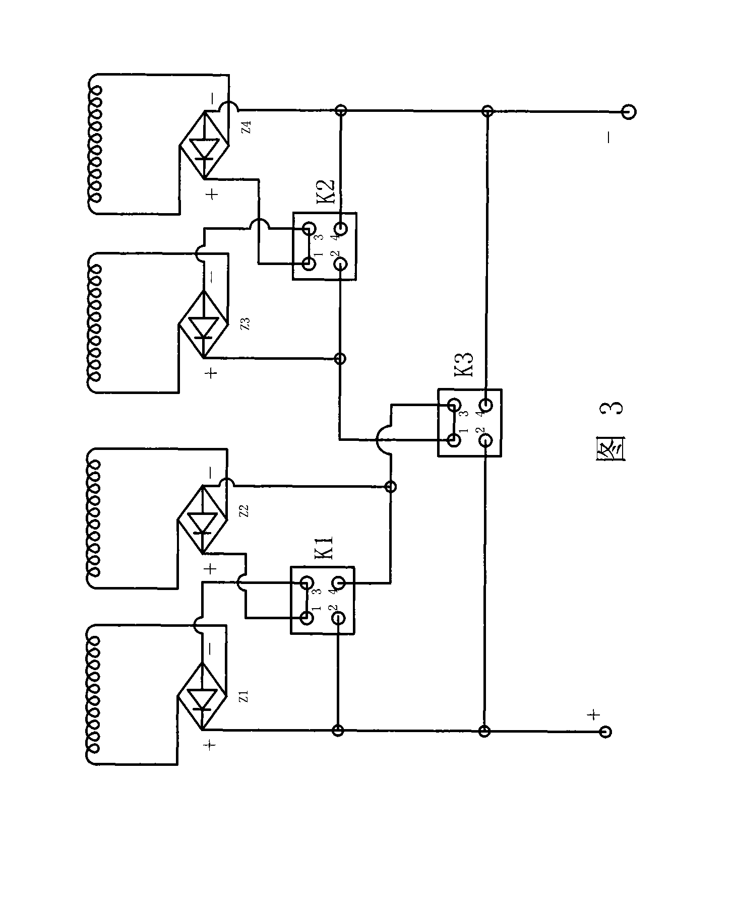
[0012] Referring to accompanying drawings 1-5, four generator units of the present embodiment are connected in series to form a generator set 2 . The main shafts 4 of the four generators in the generator set 2 are connected together with a coupling 7, and each generator is connected with a rectifier Z1-Z4, and the rectifiers Z1 and Z2 form a group, Z3 and Z4 It is a group, and they are all connected with reversing relays K1 and K2, and K1 and K2 are connected with K3.

[0013] The generator sets 2 are all mounted inside the generator casing 3, the bottom of which is welded together with the generator tower 6, one end of which is connected to the fan hub 5 through the main shaft 4, and the other end is equipped with a rotor voltage regulator 1 and Speed ​​sensor 8.

[0014] The rectification device and the reversing relay are arranged in the shape of...


PUM


Abstract

The invention relates to a generator, in particular to an electronic variable power and variable speed wind power generator, which changes the power according to the wind power. The wind power generator comprises the generator, a main shaft, a shaft coupling, a rectification device, a sensor, and a plurality of generator units, wherein, the main shaft of each generator unit is connected by the shaft coupling, each generator unit is provided with the rectification device, and each rectification device is connected with a reversal relay; and the end of the generator is provided with the sensor. The invention replaces the original given power and given voltage generator by the electronic variable power and variable speed wind power generator which is applicable to the areas with changing wind speed, and more suitable for use at sea, and has the advantages of long on-line time, high wind energy utilization rate, less additional equipments, saving investment, long use life, simple operation and convenient use.

Description

technical field [0001] The invention relates to a generator, in particular to an electronically variable power and variable speed wind power generator that changes power according to the wind force. Background technique [0002] Wind power is one of the current green energy sources for energy saving and emission reduction. At present, most of the wind turbines in production and operation in our country are products imported from foreign equipment, foreign technology or Sino-foreign joint ventures. Most of the equipment produced in the early stage was fixed propeller, constant speed gearbox, and constant power generator. This product cannot adjust the speed when the wind speed is variable. When the wind is strong, the wind generator will overspeed, causing the blades to break and the generator to be damaged. Burned out; the later products adopt blade tip reverse speed regulation, its structure is complicated, which increases the load on the blade and reduces the life of the ...

Claims


Application Information

Patent Timeline
Patent Type & Authority Applications(China)
IPC IPC(8): H02P9/48H02K13/00
CPCY02E10/725Y02E10/72
Inventor 刘旭东刘文韬
Owner 刘旭东
Learn More