Turbocharger and cylinder head

A turbocharger and cylinder head technology, which is applied to cylinder heads, cylinders, machines/engines, etc., can solve problems such as error-prone costs, difficulty in connecting turbochargers and cylinder heads, etc., to save costs and reduce installation Effects of costs and parts reduction

Inactive Publication Date: 2009-07-29
GM GLOBAL TECH OPERATIONS LLC
View PDF1 Cites 6 Cited by
  • Summary
  • Abstract
  • Description
  • Claims
  • Application Information

AI Technical Summary

Problems solved by technology

The connection of the turbocharger to the cylinder head is therefore difficult, error-prone and costly

Method used


Image

  • Turbocharger and cylinder head
  • Turbocharger and cylinder head
  • Turbocharger and cylinder head

Examples


Embodiment Construction

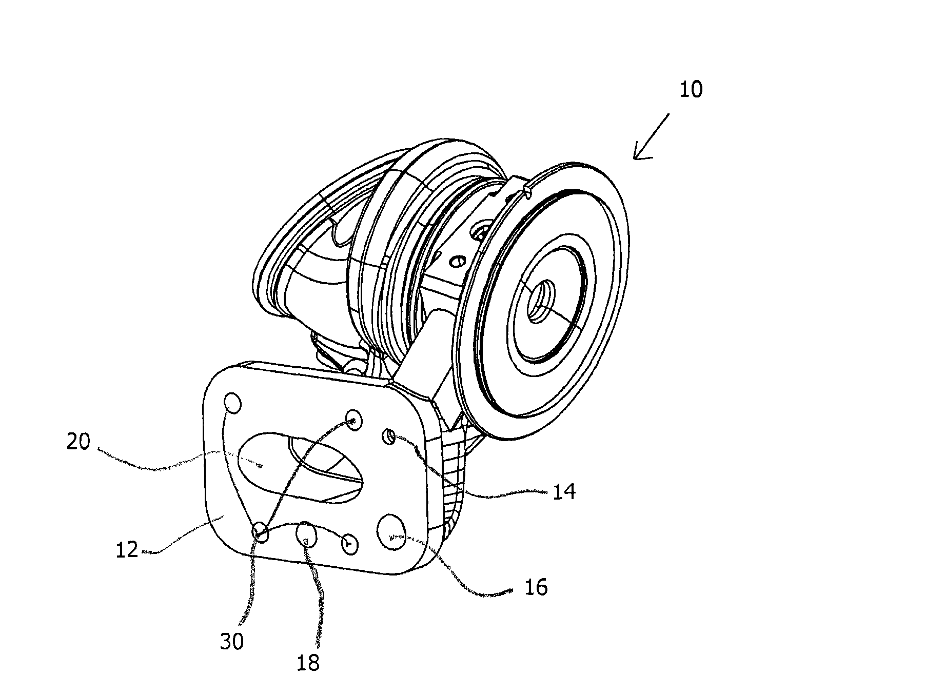
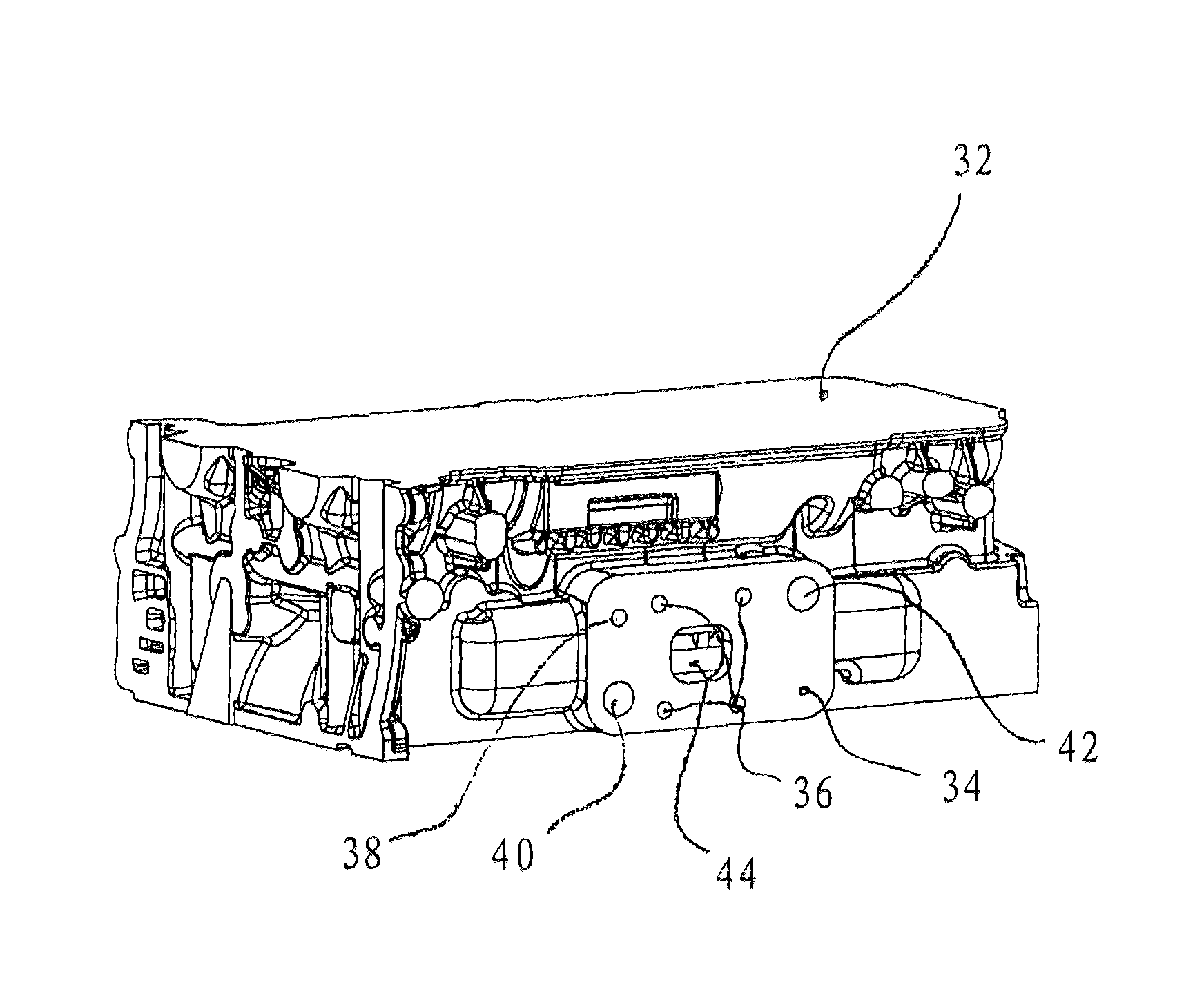
[0022] figure 1 and figure 2 The turbocharger 10 shown has a connecting flange 12 with a plurality of connecting holes 14 , 16 , 18 , 20 , wherein the connecting holes 14 , 16 , 18 , 20 can each receive a fluid for feeding and / or discharging a fluid. The fluid pipes 22, 24, 26, 28, or through the turbocharger 10 constitute. Here, the fluid lines 22 , 24 , 26 , 28 for conveying and / or discharging fluid can be, for example, the water supply line 26 of the turbocharger 10 for supplying sufficiently cold water, the pressurized oil supply line 22 , the oil return drain, etc. Oil pipe 24, exhaust gas discharge pipe 28 or crankcase fuel gas supply pipe. In the illustrated embodiment, the connection hole 14 accommodates a pressure oil supply line 22 , the connection hole 16 accommodates an oil return drain line 24 , the connection hole 18 accommodates a water supply line 26 and the connection hole 20 accommodates an exhaust gas discharge line 28 . According to the turbocharger 10 ...


PUM


Abstract

The invention relates to a turbocharger comprising a connecting flange for connection to a cylinder head, wherein the connecting flange includes at least one connection opening for receiving a fluid line for the supply and/or removal of fluids. The invention further relates to a cylinder head comprising a connecting flange for connection to a turbocharger, wherein the connecting flange has at least one connecting opening for receiving a fluid line for supplying and/or removing fluids. Moreover, an engine apparatus comprising a turbocharger with a cylinder head and a flange connected onto the cylinder head is described. Applying the invention, it is possible to connect a turbocharger and a cylinder head to one another, simply, rapidly, and straightforwardly.

Description

technical field [0001] The invention relates to a turbocharger for connecting with a cylinder head, and a cylinder head for connecting with a turbocharger. Background technique [0002] An exhaust turbocharger consists of a compressor and a turbine, which are interconnected by a common shaft. Here, a turbine driven by engine exhaust gas supplies drive energy to the compressor. To feed the exhaust gas to the turbocharger, an elbow is required in front of the turbocharger. JP 2002303145 fully discloses whether the elbow pipe is integrated with the cylinder head or the turbocharger. For the supply and discharge of oil as well as for the supply and discharge of water, the fluid pipes required for this purpose to convey and / or discharge the fluid have to be installed in several installation steps. The connection of the turbocharger to the cylinder head is therefore difficult, error-prone and costly. Contents of the invention [0003] The object of the present invention is t...

Claims


Application Information

Patent Timeline
Patent Type & Authority Applications(China)
IPC IPC(8): F02B39/14F02B37/00F02F1/24F02F1/36
CPCF02B39/14F02B67/10F01P2060/12F02B39/005F01P11/04
Inventor 简·齐默尔曼
Owner GM GLOBAL TECH OPERATIONS LLC
Why Eureka
Try Eureka