
Liquid ejecting apparatus and liquid ejecting method

A liquid and driving signal technology, applied in printing and other directions, can solve problems such as poor ink ejection

Active Publication Date: 2009-07-29
SEIKO EPSON CORP
View PDF6 Cites 2 Cited by
  • Summary
  • Abstract
  • Description
  • Claims
  • Application Information

AI Technical Summary

Problems solved by technology

If the head temperature rises excessively, ink ejection failure will occur

Method used


Image

  • Liquid ejecting apparatus and liquid ejecting method
  • Liquid ejecting apparatus and liquid ejecting method
  • Liquid ejecting apparatus and liquid ejecting method

Examples


Embodiment 2

[0113] Figure 12 It is the flow of the standby operation in Embodiment 2, Figure 13 It is a condition table of the standby operation of the second embodiment. In Embodiment 2, it is determined whether or not the drive signal generation circuit 70 executes the standby operation based on the head temperature Th and the transistor temperature Tt, and the standby time is determined.

[0114] First, when the controller 10 receives a printing command (S101), it detects the head temperature Th (S102), and detects the transistor temperature Tt (S103). Depending on the head temperature Th and the transistor temperature Tt, from Figure 13 Determine whether to execute the standby action and determine the standby time in the condition table. In addition, in the second embodiment, the standby operation is performed not for each path but for each page as in the first embodiment. When the standby operation is necessary (S104→YES / S105→NO), printing is executed after waiting for the gen...

Embodiment 3

[0122] Figure 14 This is the flow of the standby operation in the third embodiment. Figure 15A is the standby condition table of the head temperature Th corresponding to the standby action, Figure 15B is the standby condition table of the transistor temperature Tt. In the present embodiment 3, the standby time required to prevent discharge failure in the head 41 (hereinafter referred to as the first standby time T1) is determined based on the head temperature Th, and the required time to prevent the transistor from being destroyed is determined based on the transistor temperature Tt. The standby time (hereinafter referred to as the second standby time T2). Then, the first waiting time T1 (corresponding to the first waiting time) is compared with the second waiting time T2 (corresponding to the second waiting time T), and the generation of the drive signal for ink ejection is waited for longer.

[0123] First, after the printer driver receives a print command (S201), the he...


PUM


Abstract

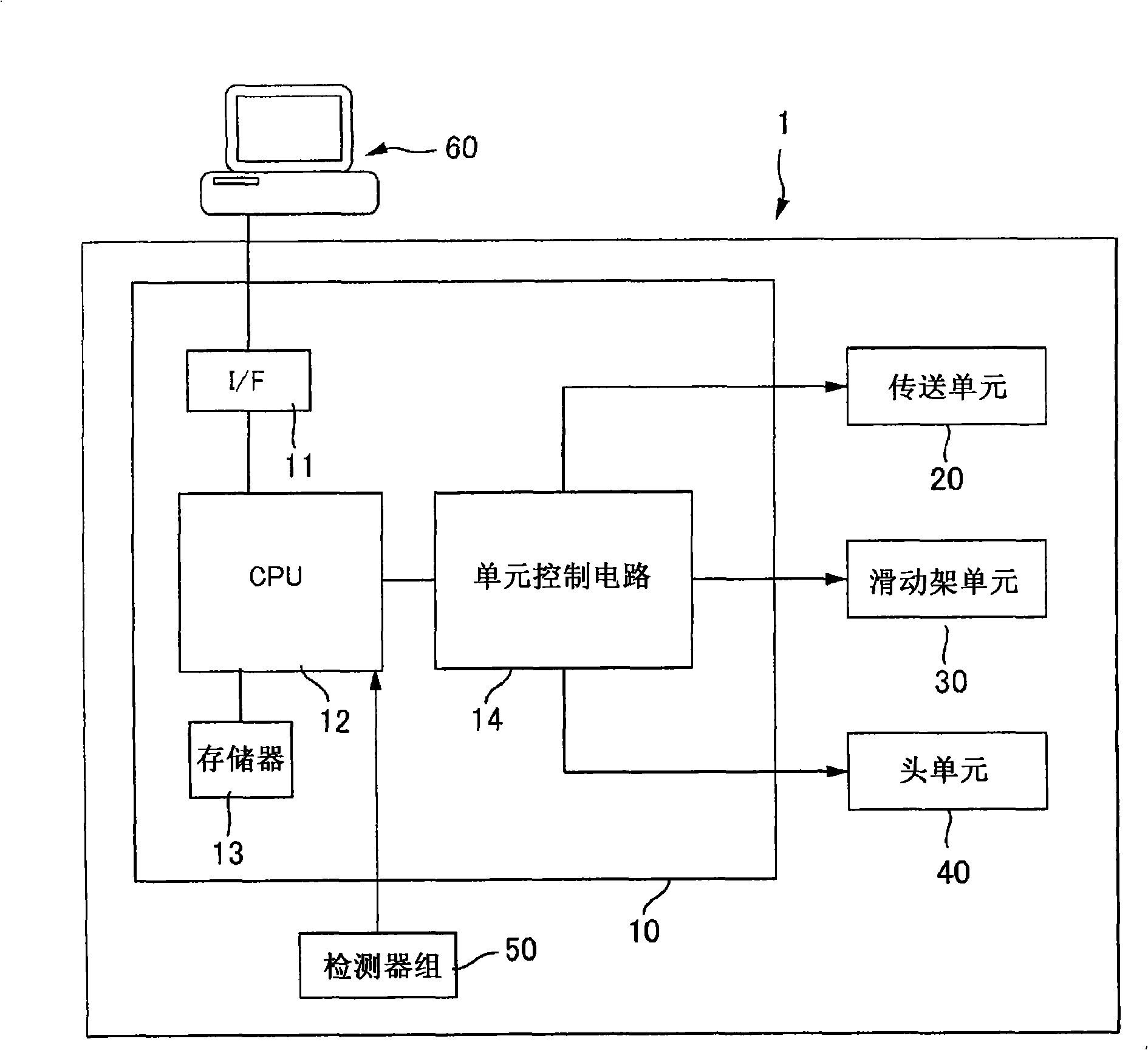
The present invention provides a liquid ejecting apparatus and a liquid ejecting method, capable of restraining ascend of head temperature. The liquid ejecting apparatus includes: a head which ejects a liquid in accordance with a driving signal; a driving signal generator which generates the driving signal; a sensor which detects the temperature of the head; and a controller which allows the headto wait the liquid ejection performed in accordance with the driving signal on the basis of the detection result of the sensor.

Description

technical field [0001] The invention relates to a liquid ejection device and a liquid ejection method. Background technique [0002] As a liquid ejection device, there is known an inkjet printer (hereinafter referred to as a printer) that ejects ink from a head by driving a drive element with a drive signal. If the drive signal generation unit that generates the drive signal continues to print for a long period of time, it generates excessive heat, which causes failure of the inkjet printer. [0003] Therefore, a method has been proposed in which a sensor is provided in the drive signal generator, and when the temperature detected by the sensor exceeds an allowable temperature, the generation of the drive signal from the drive signal generator is put on standby. (For example, refer to Patent Document 1) [0004] Patent Document 1: JP-A-2005-219462 [0005] The temperature of the heads in the same liquid ejection device also rises due to the heat generated by the drive sig...

Claims


Application Information

Patent Timeline
Patent Type & Authority Applications(China)
IPC IPC(8): B41J2/05
CPCB41J2/04563B41J2/04593B41J2/04541B41J2/0458B41J2/04581B41J2/04553B41J2/04588
Inventor 臼井寿树
Owner SEIKO EPSON CORP
Learn More