
Steel box girder assembling construction method

A construction method and technology of steel box girder, which are applied in bridges, bridge construction, erection/assembly of bridges, etc., can solve the problems of large butt joint error of assembly joints, adverse effects on urban traffic and citizens' lives, and difficulty in pier layout, etc. Guaranteed accuracy and quality, simple and easy assembly process, and reduced usage

Inactive Publication Date: 2009-07-22
GUANGZHOU MUNICIPAL ENG GROUP
View PDF0 Cites 33 Cited by
  • Summary
  • Abstract
  • Description
  • Claims
  • Application Information

AI Technical Summary

Problems solved by technology

Supporting the "hoisting unit" by means of cranes and temporary buttresses is called the "no-load" construction method, and this "no-load" construction method sometimes causes many adverse effects on urban traffic and public life
[0003] At the same time, the steel box girder routinely adopts the "no margin assembly" process, that is, the "processing unit" processed in the factory workshop and the "hoisting unit" assembled and welded on the ground on site are all processed strictly according to the size of the design drawing, without any margin , but under some special construction conditions, such as small-radius curved bridge sections, the processing accuracy of steel box girders is too high. The unexpected situation that the docking error is too large
[0004] Based on the above situation, it is necessary to design a new steel box girder assembly construction method, which can solve the problem of steel box girder margin cutting and assembly under load, ensure assembly accuracy and quality; Under restricted conditions, it is difficult to arrange temporary buttresses

Method used


Image

  • Steel box girder assembling construction method
  • Steel box girder assembling construction method
  • Steel box girder assembling construction method

Examples


Embodiment Construction

[0031] Specific embodiments of the present invention will be described below with reference to the accompanying drawings.

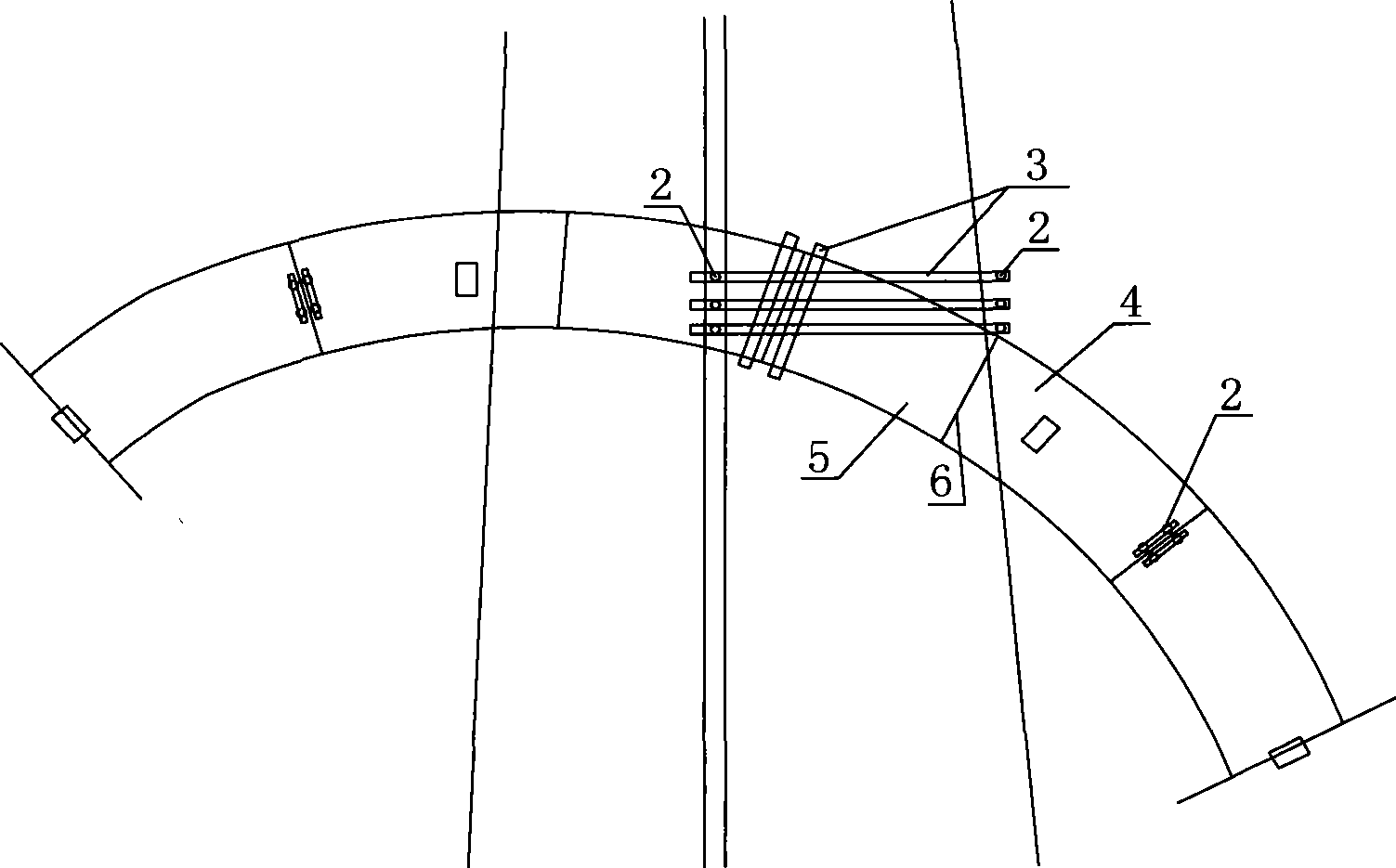
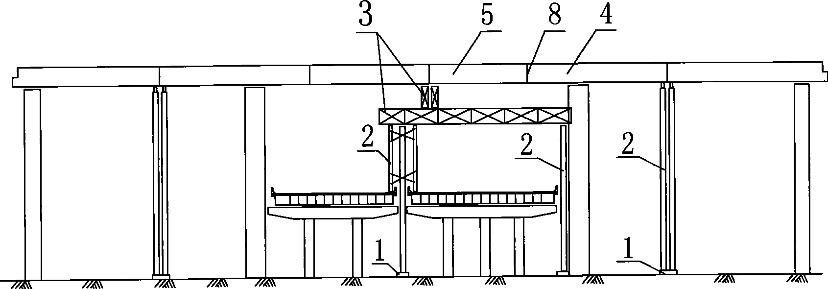
[0032] like Figure 2-5 As shown, the first embodiment includes a temporary pier foundation 1, a column 2, a pier top platform 3, a cantilever steel box girder segment 4, a rear-hanging steel box girder segment 5, a steel box girder top plate splicing joint 6, a bottom plate extension Long stiffener 7, steel box girder web splicing seam 8, U-shaped connecting clip 9, welding support 10, suspension support 11.

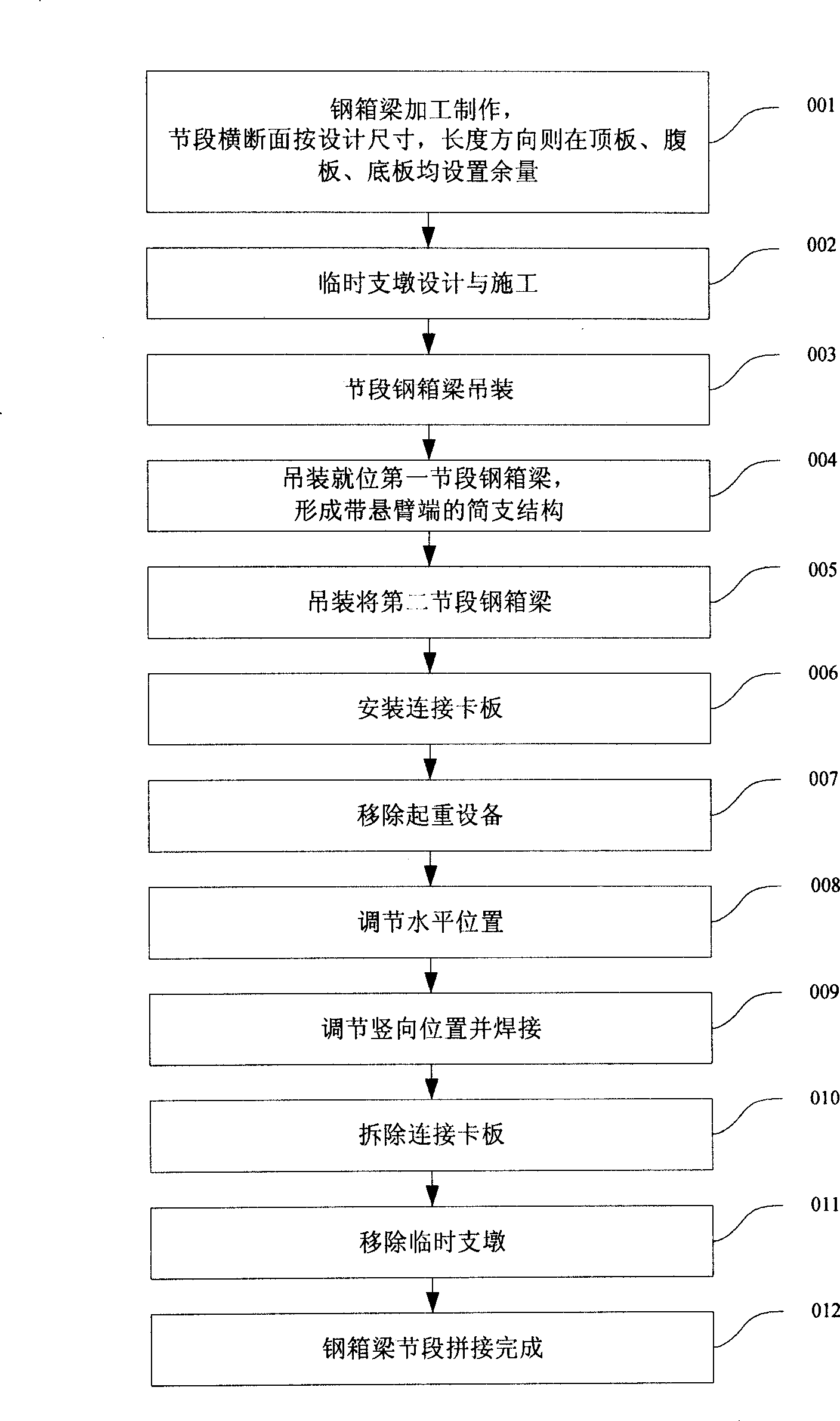
[0033] in, figure 1 This is a flow chart of the steps of the preferred embodiment 1 of the steel box girder assembling construction method of the present invention.

[0034] Step 001, the steel box girder is processed and manufactured, the cross section of the segment is according to the design size, and the length direction is set with allowances on the top plate, web plate, and bottom plate; in the processing and manufacturing stage of the stee...


PUM


Abstract

The invention provides a construction method for assembling steel box girders, which is used for the hoisting construction of the steel box girders during the road and bridge construction. The method comprises the steps as follows: a first steel box girder section is hoisted; a second steel box girder section is hoisted and suspended on the soleplate of the first steel box girder section; a connecting clamp plate is arranged at the top plate of the first steel box girder section and the second steel box girder section and is respectively suspended on top of the first steel box girder section and welded on the top of the second steel box girder section; hoisting equipment is removed; the mutual position of the steel box girder sections is adjusted and the steel box girder sections are welded to each other; the connecting clamp plate is removed; the temporary pier is removed; and the assembly is completed. As the residual assembly is adopted, the steel box girder construction under complex construction environment has large elasticity, thus ensuring the assembly precision and quality; the loading form is adopted to carry out the assembly of the steel box girder, thus solving the problem that the temporary pier is difficult to be arranged when the site is restricted; the construction time of hoisting equipment and the use of the temporary piers are reduced; and the whole assembly process is simple, feasible, safe, reliable, economical and reasonable.

Description

technical field [0001] The invention relates to a construction method in road and bridge construction, in particular to a steel box girder hoisting and assembling construction method mainly suitable for complex conditions such as old bridges and intersections in urban viaducts. Background technique [0002] At present, in the construction of roads and bridges, steel box girders are usually hoisted on temporary buttresses by sections, and assembled on site on the temporary buttresses. "unit", transport the "processing unit" to the site with large vehicles for assembly, assemble and weld into a "hoisting unit", and then hoist the "hoisting unit" into place by means of double-hoisting cranes, and install it on the temporary buttress (or On the permanent support), the hoisting unit is accurately positioned by the fine-tuning system, and assembled and welded on site to form a "whole", and finally the temporary support is removed. In the construction of roads and bridges, especia...

Claims


Application Information

Patent Timeline
IPC IPC(8): E01D21/00
Inventor 杨斌陆建忠蔡保森谢铁坚王丹洪李建明黎国明
Owner GUANGZHOU MUNICIPAL ENG GROUP
Learn More