Voltage converter and vehicle having the same
A technology of voltage conversion and power storage device, applied in battery/battery traction, output power conversion device, electric vehicle, etc., to achieve the effect of improving service life and suitable capacity
- Summary
- Abstract
- Description
- Claims
- Application Information
AI Technical Summary
Problems solved by technology
Method used
Image
Examples
no. 1 approach
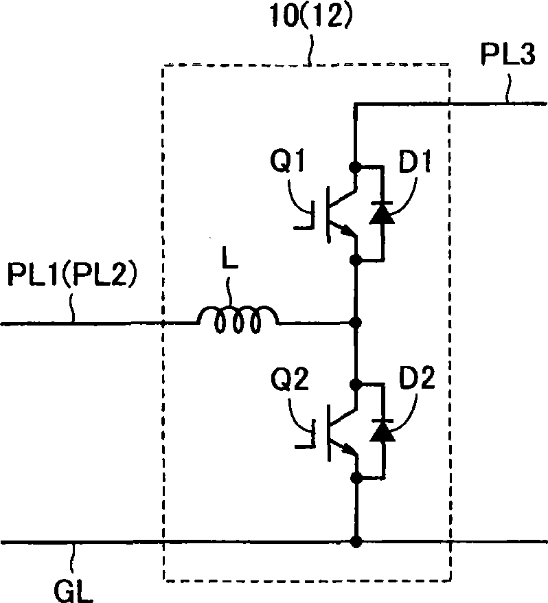
[0029] figure 1 It is an overall block diagram of a hybrid vehicle shown as an example of the vehicle of the present invention. refer to figure 1 , the hybrid vehicle 100 has an engine 2 , motor generators MG1 and MG2 , a power split mechanism 4 , and wheels 6 . In addition, the hybrid vehicle 100 further includes power storage devices B1 and B2, converters 10 and 12, capacitor C, inverters 20 and 22, ECU (Electronic Control Unit: electric control unit) 30, voltage sensors 42, 44 and 46 , Current sensors 52 and 54.
[0030] This hybrid vehicle 100 runs with engine 2 and motor generator MG2 as power sources. Power split mechanism 4 is coupled to engine 2 and motor generators MG1, MG2, and distributes power among them. The power split mechanism 4 is constituted by, for example, a planetary gear mechanism having three rotation shafts of a sun gear, a planetary carrier, and a ring gear, and the three rotation shafts are connected to the rotation shafts of the engine 4 and the ...
no. 2 approach
[0069] In the first embodiment, although the carrier signal FC2 for converter 12 is phase-shifted by 180 degrees with respect to the carrier signal FC1 for converter 10 , the phase difference between carrier signals FC1 and FC2 does not necessarily need to be 180 degrees.
[0070] Figure 8 It is a functional block diagram of the inverter control unit of the second embodiment. refer to Figure 8 , the converter control unit 32A includes a phase adjustment unit 114 instead of the Figure 4 The phase inverting unit 108' in the configuration of the converter control unit 32 of the first embodiment shown is shown.
[0071] Phase adjustment unit 114 receives carrier signal FC1 from carrier generation unit 106 and signals PWC1 and PWC2 output from comparators 110 and 112 , respectively. Furthermore, the phase adjustment unit 114 outputs the carrier signal FC2 whose phase is adjusted with respect to the carrier signal FC1 so that the rising timing of the signal PWC2 is synchronize...
PUM
 Abstract
Description
Claims
Application Information
 - R&D
- Intellectual Property
- Life Sciences
- Materials
- Tech Scout
- Unparalleled Data Quality
- Higher Quality Content
- 60% Fewer Hallucinations
Browse by: Latest US Patents, China's latest patents, Technical Efficacy Thesaurus, Application Domain, Technology Topic, Popular Technical Reports.
© 2025 PatSnap. All rights reserved.Legal|Privacy policy|Modern Slavery Act Transparency Statement|Sitemap|About US| Contact US: help@patsnap.com


