Preset voltage type high voltage frequency transformer power unit by-pass circuit for electric relay

A technology of preset voltage and bypass circuit, applied in electrical components, output power conversion devices, etc., can solve the problems of increased bypass circuit volume, low qualification rate, and reduced model selection, so as to ensure safety and reliability. sexual effect

Active Publication Date: 2010-12-15
BEIJING LEADER & HARVEST ELECTRIC TECH
View PDF3 Cites 0 Cited by
  • Summary
  • Abstract
  • Description
  • Claims
  • Application Information

AI Technical Summary

Problems solved by technology

9); but there are certain problems in this bypass circuit in practical applications; because it uses resistors R2 and R3 to connect the anode and cathode of the thyristor to the positive and negative of the DC bus respectively, so that the controllable The voltage value at both ends of the silicon is equal to the bus voltage, so that when the inverter bridge starts to work, the PWM voltage output by it will not reach both ends of the thyristor, but in practical applications, since the thyristor is not an ideal switching element, in the thyristor In the case of non-conduction, a certain DC voltage is applied between the anode and the cathode, and the thyristor will have a leakage current; usually the thyristor itself has a leakage current index, and the general manufacturer stipulates that the leakage current below 5mA is qualified. Therefore, due to the existence of leakage current, a certain current flows through the resistors R2 and R3, which leads to a certain voltage drop on the resistors R2 and R3, so the actual voltage applied to both ends of the thyristor is less than the DC bus voltage , for example, when the DC bus voltage is 1000 volts, the actual measured voltage across the thyristor only reaches 800 volts, which is caused by this reason; dv / dt; there are two ways to solve this problem: first, the resistance value of resistors R2 and R3 can be reduced, but this will increase the power consumption of the resistor and the volume of the bypass circuit; second, select the drain Thyristors with small currents will cause many thyristors with large leakage currents to be unusable in the actual production process, the room for selecting models becomes smaller, and the pass rate is low

Method used


Image

  • Preset voltage type high voltage frequency transformer power unit by-pass circuit for electric relay
  • Preset voltage type high voltage frequency transformer power unit by-pass circuit for electric relay
  • Preset voltage type high voltage frequency transformer power unit by-pass circuit for electric relay

Examples


Embodiment Construction

[0019] The present invention will be further described below in conjunction with the accompanying drawings and embodiments.

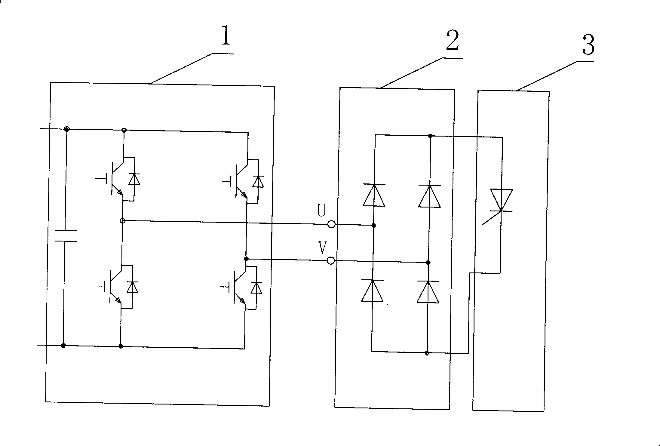
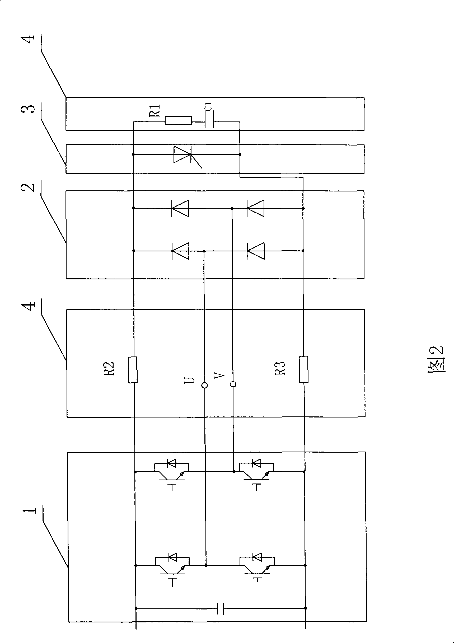
[0020] Such as image 3 As shown, the power unit includes a bypass circuit for the H inverter bridge 1 composed of a diode rectifier bridge 2 , a thyristor 3 and a preset voltage circuit 4 . Wherein the diode rectifier bridge 2 and the silicon controlled rectifier 3 are prior art, and will not be described in detail here. The preset voltage circuit 4 includes: current limiting resistors R2, R3, relays KC1, KC2, fuses FU1, FU2, charging resistor R1, and charging capacitor C1.

[0021] Wherein, the current-limiting resistor R2, the relay KC1, and the fuse FU1 are sequentially connected in series between the DC positive bus of the H inverter bridge 1 and the thyristor 3 . The current limiting resistor R3, the relay KC2, and the fuse FU2 are sequentially connected in series between the DC negative bus of the H inverter bridge 1 and the thyristor 3. The r...


PUM


Abstract

The invention provides a bypass circuit for a power unit of the preset voltage type high voltage inverters of a relay. The bypass circuit comprises a diode rectification bridge parallel connected beside an H inversion bridge, and a controlled silicon, and is characterized in that a preset voltage circuit is further arranged; the preset voltage circuit comprises at least one relay, at least one charge resistor, current-limiting resistor and charging capacitor; the relay and the current-limiting resistor are connected in parallel between DC positive busbar or negative busbar of the power unit and the controlled silicon; the charge resistor and the charging capacitor are connected in parallel beside the controlled silicon after being connected in series. In the bypass circuit with such structure, the voltages of two ends of the controlled silicon is preset to be close to the voltage value of the busbar under the condition that the bypass circuit is not provided to power unit; the diode rectification bridge and the controlled silicon in the bypass circuit no longer bear dv / dt exceeding endurance capacity thereof when the power unit operates; therefore the safety and the reliability ofthe inverter are ensured, and the fault of the power unit can be effectively bypassed.

Description

technical field [0001] The invention relates to a bypass circuit, in particular to a relay preset voltage type high-voltage inverter power unit bypass circuit, which belongs to the technical field of electrical automation equipment. Background technique [0002] With the rapid development of modern power electronics technology and microelectronics technology, high-voltage and high-power frequency conversion speed control devices continue to mature; especially when the reliability of high-voltage device applications is not too high and the price is high, in recent years people This problem has been well solved by means of unit series connection, so the field and scope of application of unit series multi-level high-voltage inverters are becoming wider and wider, which makes efficient and reasonable use of energy (especially electric energy) ) became possible. [0003] During the operation of the series-connected multi-level high-voltage inverter, one or several power units ma...

Claims


Application Information

Patent Timeline
Patent Type & Authority Patents(China)
IPC IPC(8): H02M1/32
Inventor 朱燕华马永健
Owner BEIJING LEADER & HARVEST ELECTRIC TECH
Why Eureka
Try Eureka