Time division multiplexing optical fiber sensing apparatus
A technology of optical fiber sensing and time division multiplexing, which is applied in the direction of transmitting sensing components with optical devices, can solve the problems of small number of optical fiber sensors and complex wavelength demodulation equipment, and achieve the goal of increasing the number of sensors, simplifying the structure and reducing the price Effect
- Summary
- Abstract
- Description
- Claims
- Application Information
AI Technical Summary
Problems solved by technology
Method used
Image

Examples
specific Embodiment approach 1
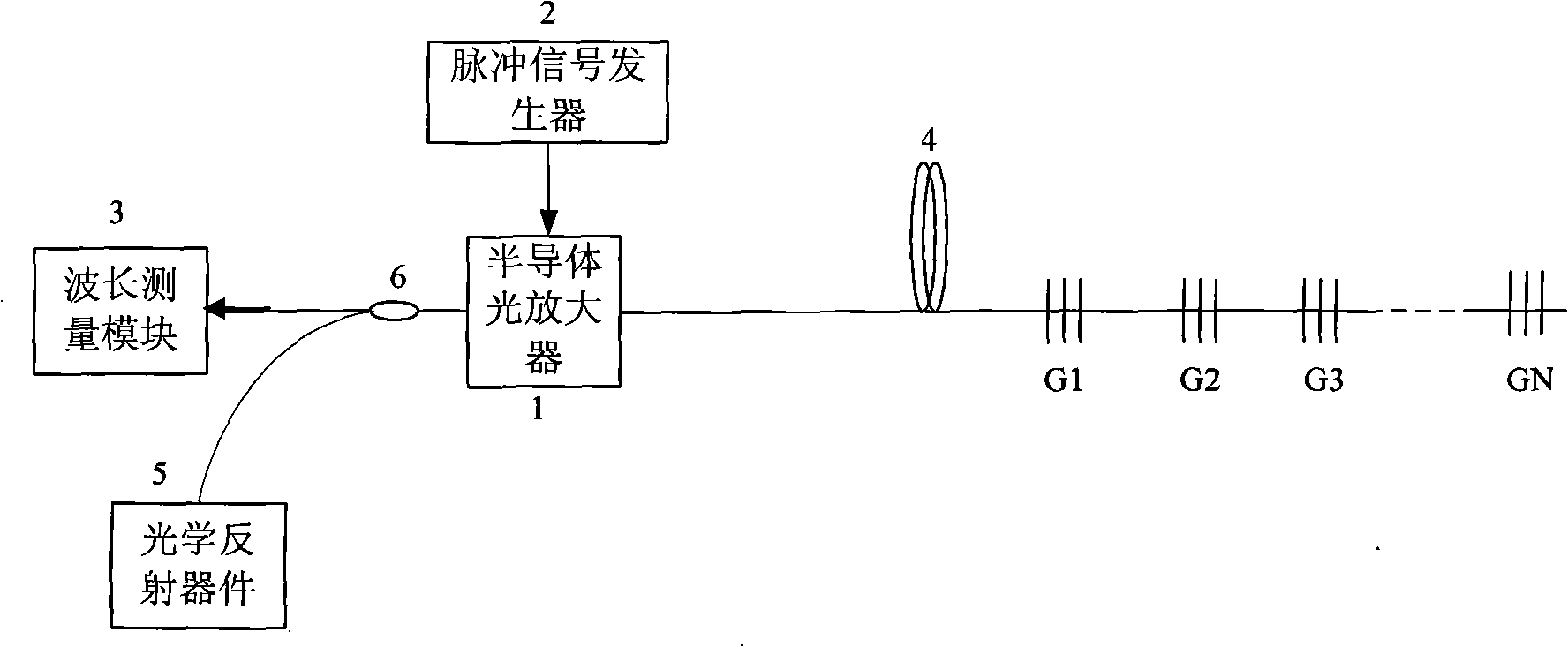
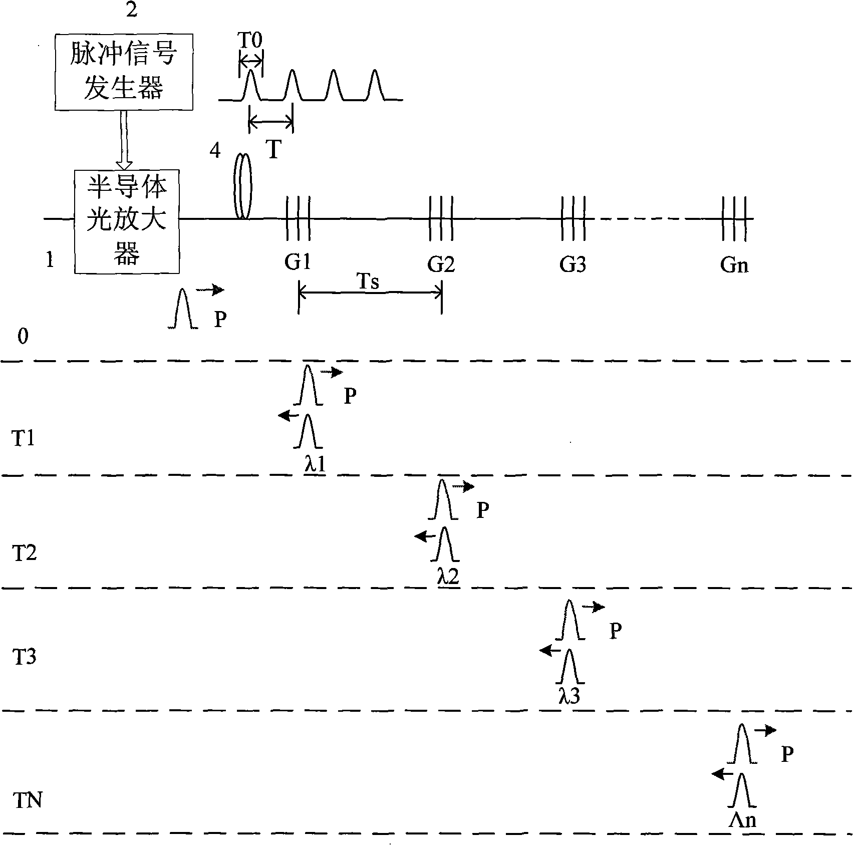
[0009] Specific implementation mode one: the following combination figure 1 This embodiment will be specifically described. The method of this embodiment is composed of the following steps: 1. Using a semiconductor optical amplifier to generate a pulsed light signal to enter the sensor array; the sensor array is composed of a plurality of sensors connected in series through an optical fiber, and the sensors are low reflection The center wavelength of multiple fiber gratings is the same; second, the pulsed optical signal is reflected back to the semiconductor optical amplifier by each sensor in turn, and the optical signal reflected by a certain sensor is selectively passed through by controlling the switching time of the semiconductor optical amplifier; 1. After the signal passing through the semiconductor optical amplifier is amplified, it enters the wavelength measurement module to realize the wavelength measurement of the selected sensor.
[0010] The device of this embodi...
specific Embodiment approach 2
[0015] Specific implementation mode two: the following combination figure 1 This embodiment will be specifically described. The difference between this embodiment and Embodiment 1 is that in step 3 of the method, the optical signal amplified by the semiconductor optical amplifier is partially reflected back to the sensor array by the optical reflection device, and then reflected back by the sensor array, and passes through the semiconductor optical amplifier. After being amplified, it is reflected by the optical reflective device, and this is repeated many times until the semiconductor optical amplifier is saturated; the optical signal transmitted through the optical reflective device enters the wavelength measurement module to realize the wavelength measurement of the sensor.
[0016]Since the sensor array is composed of multiple sensors connected in series, each sensor must be a low-reflectivity grating to ensure that the signal transmitted to the remote sensor is not excess...
specific Embodiment approach 3
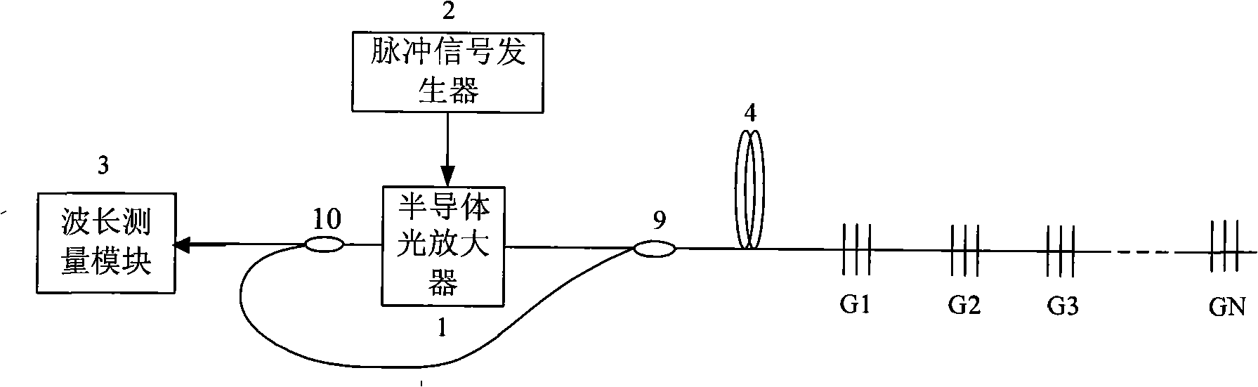
[0017] Specific implementation mode three: the following combination image 3 This embodiment will be specifically described. The difference between this embodiment and Embodiment 1 is: its device also includes No. 1 coupler 9 and No. 2 coupler 10, No. 2 coupler 10 is a 20:80 coupler, wavelength measurement module 3 and No. 2 coupler 20% of the splitting end of No. 10 is connected, and 80% of the splitting end of No. 2 coupler 10 is connected with a splitting end of No. 1 coupler 9, and another splitting end of No. 1 coupler 9 is connected with the reflected signal of semiconductor optical amplifier 1. The input end is connected, the other end of the first coupler 9 is connected with one end of the fiber ring 4 , and the other end of the second coupler 10 is connected with the amplified signal output end of the semiconductor optical amplifier 1 .
[0018] In this embodiment, taking the addressable sensor G1 as an example, the period of the pulse signal generator 2 outputting ...
PUM
 Abstract
Description
Claims
Application Information
 - R&D
- Intellectual Property
- Life Sciences
- Materials
- Tech Scout
- Unparalleled Data Quality
- Higher Quality Content
- 60% Fewer Hallucinations
Browse by: Latest US Patents, China's latest patents, Technical Efficacy Thesaurus, Application Domain, Technology Topic, Popular Technical Reports.
© 2025 PatSnap. All rights reserved.Legal|Privacy policy|Modern Slavery Act Transparency Statement|Sitemap|About US| Contact US: help@patsnap.com