
Agitating friction riveting device and riveting method

A friction stir and riveting device technology, applied in welding/welding/cutting items, welding equipment, non-electric welding equipment, etc., can solve the problem of point-fixed joints not being strong enough, and achieve the effect of excellent room temperature plasticity and excellent connection quality

Inactive Publication Date: 2009-07-01
INST OF METAL RESEARCH - CHINESE ACAD OF SCI
View PDF0 Cites 49 Cited by
  • Summary
  • Abstract
  • Description
  • Claims
  • Application Information

AI Technical Summary

Problems solved by technology

This method will leave a hole in the center of the point-fixed joint. For high-strength steel plates, the point-fixed joint is still firm, but for light-weight plates such as aluminum alloys and magnesium alloys, the point-fixed joint is not strong enough.

Method used

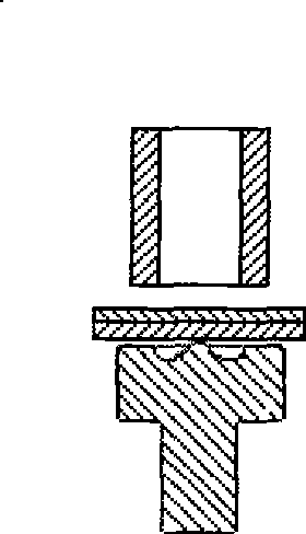
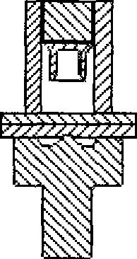
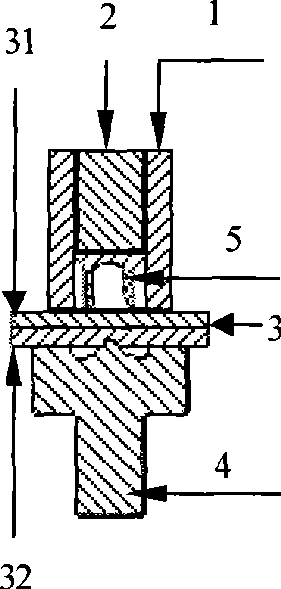

Image

  • Agitating friction riveting device and riveting method
  • Agitating friction riveting device and riveting method
  • Agitating friction riveting device and riveting method

Examples


Embodiment

[0035] 1. Friction stir riveting of LF2 aluminum alloy sheet

[0036] Plate specification: 2mm+2mm.

[0037] Rivet II material, size, shape and surface condition: the material is high-strength carbon structural steel, the height is 4mm, the diameter of the nail cover is 8mm, the diameter of the nail bottom is 4mm, and the diameter of the nail neck is 3mm. Both the cap and the bottom of the rivet are flat, and there is a groove I in the shape of a "ten" on the cap, the neck of the nail has no groove, and the surface of the rivet II has no coating.

[0038] The shape and size of the rivet rotary drive rod: the top of the end adopts the shape of a "ten" screwdriver head, and the diameter of the shaft shoulder is 11mm.

[0039] The shape and size of the groove II of the rigid gasket: the groove II is in the shape of a truncated cone, the diameters of the upper and lower bottom surfaces are 8mm and 7mm, and the depth is 1mm. Both the upper and lower bottom surfaces of the circular...


PUM


Abstract

The invention relates to a fixedly-connecting technique for board points, in particular to a stirring, rubbing and riveting device and a riveting method. The device comprises a driving rod, a rivet II and a rigidity pad, wherein the driving rod which can be matched with the rivet II and drive the rivet II to rotate is arranged above the rivet; the rigidity pad is arranged below the rivet II; the driving rod is matched with the rivet II; and a board is arranged between the rivet II and the rigidity pad. The method comprises: firstly, aligning the rigidity pad and the driving rod; secondly, placing the connected board and the rivet II in sequence, lifting the driving rod down, making the driving rod matched with the rivet II completely, and starting the driving rod to drive the rivet II to rotate synchronously; heating and softening the local of the connected board under the action of the pressure and rubbing heat, making a local material of the connected board fully flow under the action of the rubbing heat and mechanical stir along with continual rotating and down-moving of the rivet II; and filling a groove II on the rigidity pad and a rivet neck space of the rivet II to realize metallurgical bonding of the rivet II and the board and complete stirring, rubbing and riveting joints.

Description

Technical field: [0001] The invention relates to a spot-fixed connection technology for plates, in particular to a friction stir riveting device and a riveting method. Background technique: [0002] Resistance spot welding and riveting have always been the main methods for spot-fixed connection of sheet metal, and are widely used in various industrial fields. In recent years, the international pressure on energy and environmental protection has been increasing, and the automotive industry urgently needs to reduce the weight of the body to reduce fuel consumption and exhaust emissions. Substituting light alloys such as aluminum alloys and magnesium alloys for steel bodywork is an effective way to reduce the weight of the bodywork. There are great difficulties in spot-solid joining of aluminum alloy and magnesium alloy plates by traditional resistance spot welding method. On the one hand, the sticking loss of the spot welding electrode is serious, and it is difficult to adap...

Claims


Application Information

Patent Timeline
IPC IPC(8): B23K20/12B23K103/16
CPCB21J15/027
Inventor 郝传勇张劲松罗华李正林毛先锋张洪延
Owner INST OF METAL RESEARCH - CHINESE ACAD OF SCI
Learn More