
Minitype paster fuse and method of manufacturing the same

A fuse and patch technology, applied in fuse manufacturing, emergency protection devices, electrical components, etc., can solve problems affecting resistance, electrical performance consistency, penetration, etc., and achieve the effect of inhibiting penetration and thermal insulation penetration.

Inactive Publication Date: 2009-06-24
SHANGHAI CHANGYUAN WAYON CIRCUIT PROTECTION CO LTD
View PDF1 Cites 12 Cited by
  • Summary
  • Abstract
  • Description
  • Claims
  • Application Information

AI Technical Summary

Problems solved by technology

[0003] However, during the co-firing process, the internal electrode will penetrate into the glass ceramic matrix, which will affect the consistency of its resistance value and electrical properties.

Method used


Image

  • Minitype paster fuse and method of manufacturing the same
  • Minitype paster fuse and method of manufacturing the same
  • Minitype paster fuse and method of manufacturing the same

Examples


Embodiment 1

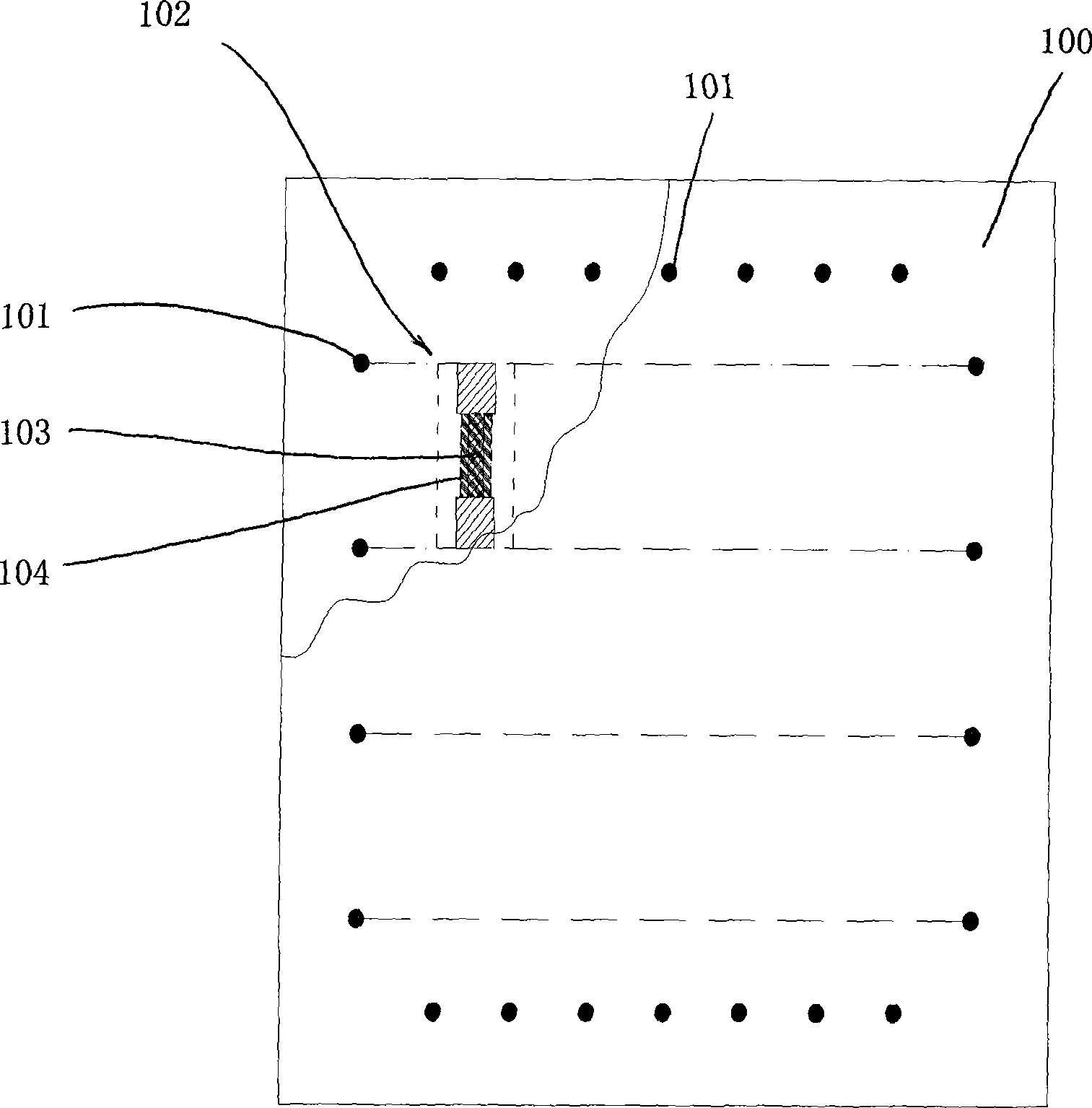
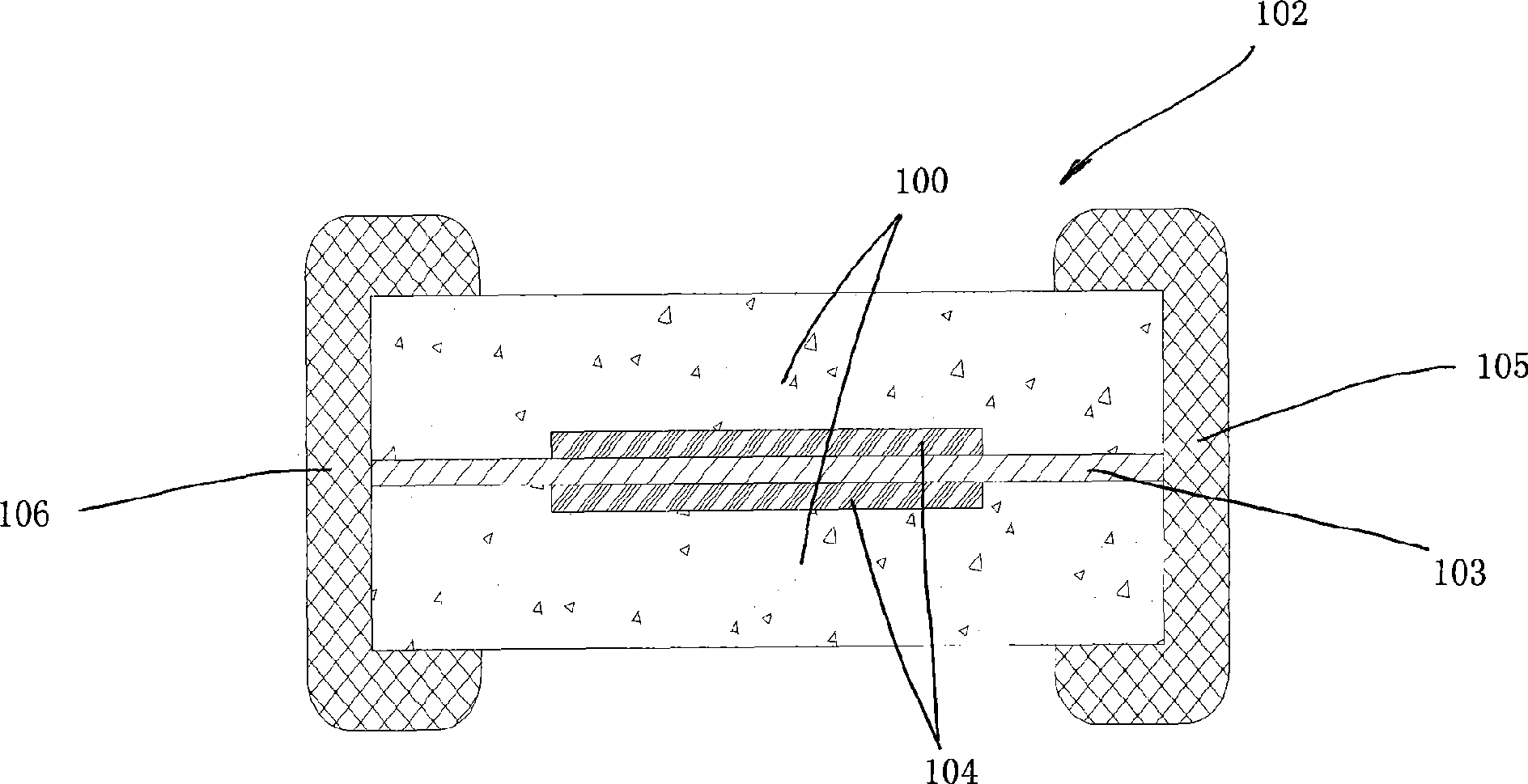
[0024] see figure 1 It is the top view structure schematic diagram of the raw film of the present invention and figure 2 It is a schematic diagram of the side section structure of the small patch fuse of the present invention.

[0025] A small chip fuse 102, with a glass ceramic layer 100 as a substrate, and the material of the glass ceramic layer 100 is one of alumina, titanium dioxide, calcium aluminosilicate, alumina, borosilicate glass, calcium borosilicate or A variety of mixtures; use the fuse metal or alloy as the internal electrode 103 to form a monolithic structure, and the material of the internal electrode 103 is a metal or an alloy of multiple metals among gold, silver, copper, aluminum, palladium, and platinum; monolithic Both ends of the structure are provided with terminal electrodes 105,106.

[0026] A layer of internal electrodes 103 is arranged between the two layers of glass ceramic layers 100. The two ends of the internal electrodes 103 are in contact wi...

Embodiment 2

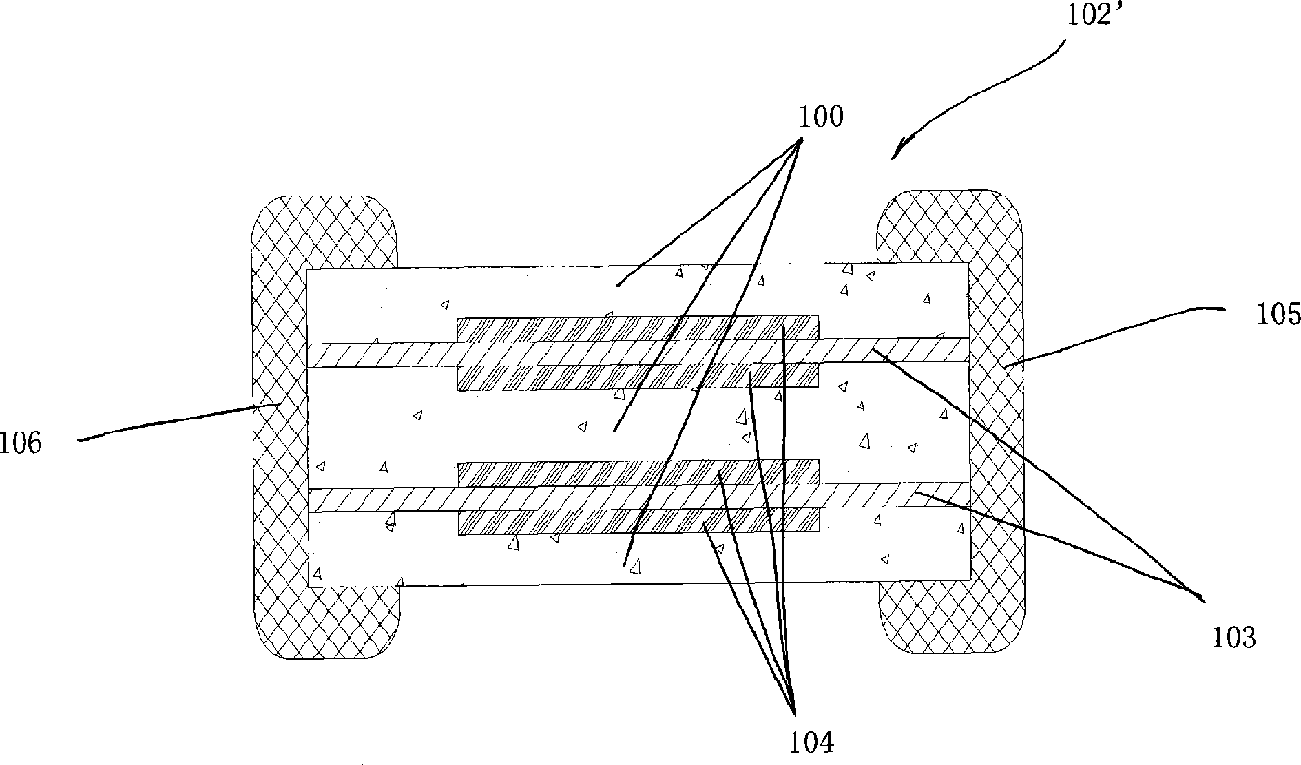
[0030] see image 3 As shown in the schematic diagram of the side sectional structure of the small chip fuse according to Embodiment 2 of the present invention, a small chip fuse 102' is based on a glass ceramic layer 100, and the material of the glass ceramic layer 100 is alumina, titanium dioxide, aluminosilicate A mixture of one or more of calcium salt, alumina, borosilicate glass, and calcium borosilicate; a monolithic structure is formed with a fuse metal or alloy as the internal electrode 103, and the material of the internal electrode 103 is gold, silver, or copper , aluminum, palladium, platinum or a metal alloy; the two ends of the monolithic structure are provided with terminal electrodes 105,106.

[0031] Two layers of internal electrodes 103 are arranged between the three layers of glass ceramic layers 100. Both ends of the two layers of internal electrodes 103 are in contact with terminal electrodes 105 and 106 respectively. The middle part of the internal electro...


PUM


Abstract

The invention relates to a small patch fuse and a manufacturing method, in particular to a small patch fuse which can improve the electrical properties, and a manufacturing method thereof. The small patch fuse takes a glass-ceramic layer as the substrate and takes the fuse metal or alloy as the internal electrodes to form a monolithic structure; both end parts of the monolithic structure are provided with end electrodes, wherein, one or more layers of internal electrodes are arranged between two glass-ceramic layers; both ends of each internal electrode are contacted with each end electrode; the middle part of the internal electrode is a fuse part; the upper and lower surfaces of the internal electrode are respectively provided with attached glaze layers; the attached glaze layers cover the entire fuse part of the internal electrode; besides, the length and width of the attached glaze layers are less than the length and width of the monolithic structure. The attached glaze layers can prevent the internal electrodes and the ceramic body penetrating each other in the co-firing process and improve the consistency of product resistance and electrical properties, and also achieve the effect of thermal insulation, so that the fuse part can quickly and effectively act.

Description

technical field [0001] The invention relates to a small chip fuse and a manufacturing method thereof, in particular to a small chip fuse with improved electrical performance and a manufacturing method thereof. Background technique [0002] Due to the requirements of production accuracy, the small chip fuse with a monolithic structure usually only prints one or more layers of internal electrodes, and then separates them with a glass-ceramic body. The applicant of the present invention discloses a chip type fuse in its Chinese Patent Publication No. CN101202186, which cuts a slit in the width direction of the glass ceramic substrate, so that the metal thin film material used as the internal electrode extends from between the substrates to the end surface of the substrate, and then The terminal electrode is changed to change the line-surface contact between the internal electrode and the terminal electrode into surface-surface contact, thereby improving the contact strength. ...

Claims


Application Information

Patent Timeline
IPC IPC(8): H01H85/055H01H85/08H01H85/06H01H69/02
Inventor 杨彬王孝奎沈十林钱朝勇张子川
Owner SHANGHAI CHANGYUAN WAYON CIRCUIT PROTECTION CO LTD
Learn More