
Method and special equipment for recycling to produce fuel

A technology of organic waste and special equipment, used in special forms of dry distillation, petroleum industry, coke ovens, etc., can solve the problems of non-continuous normal operation, cumbersome process and equipment, uneven heating of organic waste, etc. The effect of small internal volume and reduced replacement frequency

Active Publication Date: 2009-06-24
CHAOYANG SHENYUAN ACTIVE CARBON
View PDF2 Cites 9 Cited by
  • Summary
  • Abstract
  • Description
  • Claims
  • Application Information

AI Technical Summary

Problems solved by technology

The technological process and equipment of this technology are cumbersome, consume a lot of energy, the post-treatment process is backward, the production cycle is long, and the efficiency is low, so it is not suitable for a large amount of continuous treatment of organic waste.
[0003] Among the currently used organic waste recycling and processing equipment, single (thick) tube or kettle type heating and cracking are mostly used, such as tube heating, a large amount of organic waste is unevenly heated and causes local blockage. The more serious it is, the scale and coking of the slag on the wall will occur during the operation, causing local overheating and deformation of the equipment, so that the continuous normal operation cannot be performed. So far, this technical problem has not been solved.

Method used

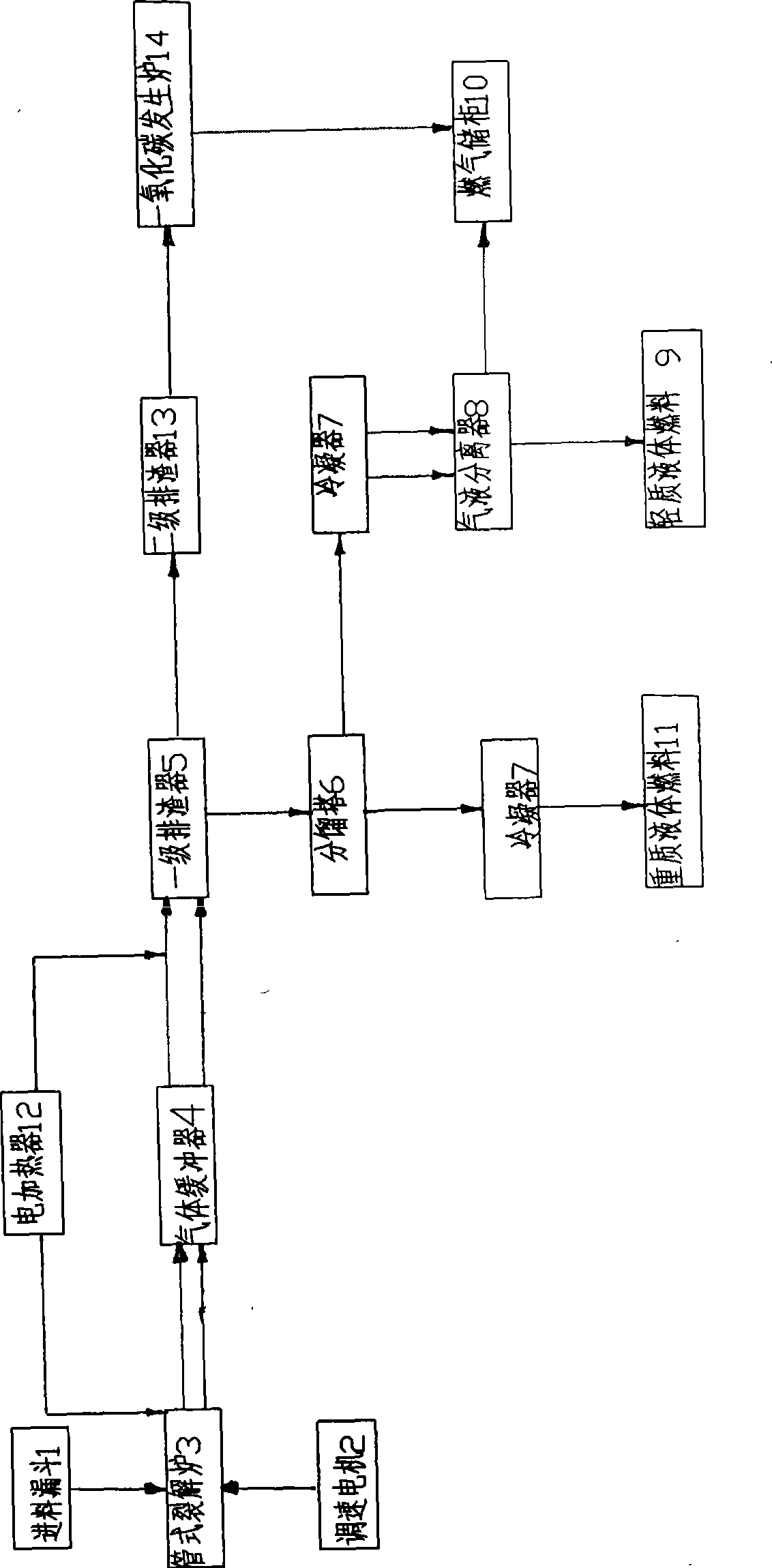
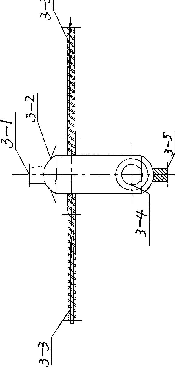
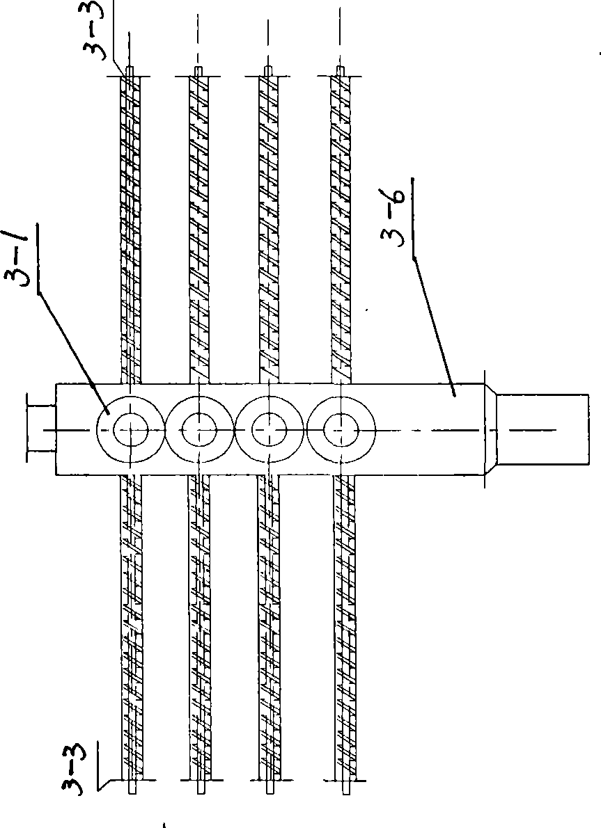

Image

  • Method and special equipment for recycling to produce fuel
  • Method and special equipment for recycling to produce fuel
  • Method and special equipment for recycling to produce fuel

Examples


Embodiment Construction

[0019] See figure 1 , Separate the domestic garbage to remove metal and inorganic matter, separate the organic garbage, and pass the organic garbage from the feed hopper 1 through the conveying tubes 3-3 on both sides of the tubular cracking furnace 3 to the furnace to the collector 3-6 In the middle push, the advancing speed is 60~65 rpm, heating and depolymerizing at the temperature of 220~240℃, the spiral hinge rod is installed in the conveying tube 3-3, and the material is expanded to the middle of the cracking furnace controlled by the speed regulating motor 2. The radial concentrators 3-6 are advanced, and the electric heating device 12 respectively heats up and heats the conveying tube, the cracking furnace concentrator and the concentrating pipeline between the primary slag discharger.

[0020] The gas material depolymerized by the cracking furnace first enters the gas buffer 4, and the inner wall of the buffer 4 is provided with staggered baffles. The gas flow direction ...


PUM


Abstract

The invention relates to a method and a special equipment for recycling organic wastes to generate fuels. The method is as follows: the organic wastes are delivered from two ends of a feed delivery tube [3-3] to a tube cracking furnace [3] and finally to a collector with a heating device, followed by thermal depolymerization at the temperature ranging from 200 to 240 DEG C; the depolymerized gasified material enters a primary discharging unit [5] for cracking at the temperature ranging from 200 to 240 DEG C via the collector, and enters a fractionating tower [6], the un-gasified material is subjected to the thermal cracking at the temperature ranging from 240 to 350 DEG C until the process of the catalytic cracking is completed at the temperature ranging from 420 to 450 DEG C, the gas-liquid fuel is obtained via post-treatments. The tube cracking furnace solves the difficult technical problems in the heating and feeding production of current kettle-type thick tubes, is heated uniformly without congestion, realizes consecutive production operation and can treat 60-90T of the organic wastes per day with the recycling rate reaching over 50%. The primary discharging unit is high in the strength of the apparatus and free from dead corners and residual slag when delivering the materials, which avoids the apparatus from local overheating and deformation due to scale formation and coking, furthermore, the unit has small volume, high safety factor in the production process and low replacement frequency of the unit and the components thereof.

Description

Technical field [0001] The invention belongs to the field of garbage treatment, in particular to the technology and special equipment for producing fuel from recycled organic garbage. Background technique [0002] The scientific utilization and innocuous treatment of urban waste have always been attached importance to by all countries. The waste has been improved from incineration and landfill to recycling and reuse. In particular, the technology and equipment for recycling organic waste as fuel have been reported. CN1204227C "fuel-derived garbage disposal device", this technology first removes the air in the garbage materials, and in the thermal cracking light, under vacuum conditions, the hot air current is reversed to contact the materials at 400-700°C. Carry out thermal cracking, and then purify and filter the fuel gas. The disadvantage is that only part of the organic matter is recovered as fuel gas, and the ungasified part and a small amount of combustion products are not r...

Claims


Application Information

Patent Timeline
IPC IPC(8): C10B53/00
Inventor 仲伟洲李国君
Owner CHAOYANG SHENYUAN ACTIVE CARBON
Learn More