
Heavy duty dumper

A technology of unloading car and guide chute, applied in the direction of conveyor, mechanical conveyor, conveyor objects, etc., to achieve the effect of prolonging service life, simple structure and reducing vibration

Inactive Publication Date: 2009-06-24
SHENYANG MINING MACHINERY GROUP
View PDF0 Cites 3 Cited by
  • Summary
  • Abstract
  • Description
  • Claims
  • Application Information

AI Technical Summary

Problems solved by technology

Ordinary unloading trucks are only suitable for belt conveyors with a bandwidth of ≤1400mm and a bulk density of ≤1600Kg / m 3 materials, suitable for belt speed ≤ 2.5m / s

Method used

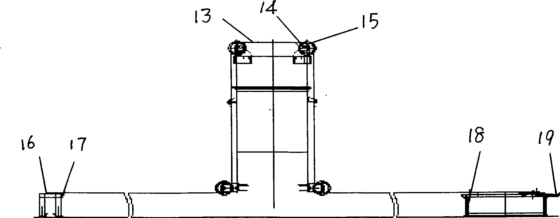

Image

  • Heavy duty dumper
  • Heavy duty dumper
  • Heavy duty dumper

Examples


Embodiment Construction

[0011] It has a driving traveling device 12, a main belt, and two side chutes 11 connected to the funnel 2, and directly below the funnel are a material guide chute, a material receiving buffer device and a main belt 10, see figure 2 , the said trough has a wear-resistant liner 4 on the inner side of the side plate 3 of the trough to prevent the material from scratching the side plate of the trough, and there is an adjustable rubber at the lower end of the side plate of the trough Plate 5, the adjustable rubber plate 5 is fixed by the pressure plate 6, and the rubber plate 5 can be adjusted downward at any time to ensure the sealing of the lower part and prevent the material from leaking here. The buffer device has a buffer roller frame body 8 and a buffer roller group 7. A rubber ring is installed on the surface of the buffer roller. When the material needs to be unloaded on the main belt, the material falls on the buffer device through the funnel and the guide groove. , to ...


PUM


Abstract

The invention provides a heavy-duty dumper, which aims to solve the problem that the prior dumper is only suitable for low-power sealing-tape machines and is not suitable for high-power belt conveyers used by large-scale enterprises such as large-scale power stations. The key points of the heavy-duty dumper comprise the following: the heavy-duty dumper is provided with a main belt and two side chutes which are connected with a hopper; a guide chute, a receiving buffer device and the main belt are arranged under the hopper in turn; the buffer device is provided with a buffer roller frame body and a buffer roller set; rubber rings are arranged on surfaces of buffer rollers; a driving running gear adopts a variable-frequency motor; a sealing device is arranged inside each side chute and consists of an adhesive tape provided with a framework, a bearing roller, a clamping device, a tensioning device, a support, a clamping device support and a tensioning device tailstock; the bearing roller is fixed on a chute body; the special adhesive tape provided with the framework passes by the bearing roller; and a sealing adhesive tape is arranged above a bin opening by which discharged materials of the chute pass and passes by two side walls and the upper part of the chute. The heavy-duty dumper is suitable for the belt conveyers which are operated in high power.

Description

technical field [0001] The invention relates to a material conveying device, in particular to a heavy-duty unloading vehicle for a belt conveyor. Background technique [0002] The unloading truck is used for unloading at any point in the horizontal section. Ordinary unloading trucks are only suitable for belt conveyors with a bandwidth of ≤1400mm and a bulk density of ≤1600Kg / m 3 For materials, the applicable belt speed is ≤2.5m / s. Realize single-side unloading and simultaneous unloading on both sides. At present, large-scale power plants, raw material plants, and steel plants use large bandwidth, bandwidth B=1200~2200mm, large capacity Q=10000t / h, bulk density ≥ 1600Kg / m3, high belt speed ≤ 6m / s, high power operation High-quality belt conveyors need heavy-duty unloading trucks to transport materials. Contents of the invention [0003] The object of the present invention is to provide a heavy-duty unloading vehicle suitable for a belt conveyor with high-power operation...

Claims


Application Information

Patent Timeline
Patent Type & Authority Applications(China)
IPC IPC(8): B65G41/02B65G37/00
CPCY02P70/10
Inventor 陶忠坤任杰赵奎波陶忠革刘淑玉张丽郝演鲁马爱华原丽朱艳
Owner SHENYANG MINING MACHINERY GROUP
Learn More