Fan frame

A fan frame and fan technology, applied to parts of pumping devices for elastic fluids, non-variable pumps, machines/engines, etc., can solve problems such as operational troubles, increase production efficiency, and facilitate disassembly and assembly. The effect of reducing manufacturing costs

Active Publication Date: 2011-05-04
DELTA ELECTRONICS INC
View PDF2 Cites 0 Cited by
  • Summary
  • Abstract
  • Description
  • Claims
  • Application Information

AI Technical Summary

Problems solved by technology

And after overhaul or heavy work are finished, must again fix wire rod W with new drawstring 12
Such a complicated operation process causes troubles in operation

Method used


Image

  • Fan frame
  • Fan frame
  • Fan frame

Examples


Embodiment Construction

[0025] The fan frame of the preferred embodiment of the present invention will be described below with reference to related drawings, wherein the same components are denoted by the same reference numerals.

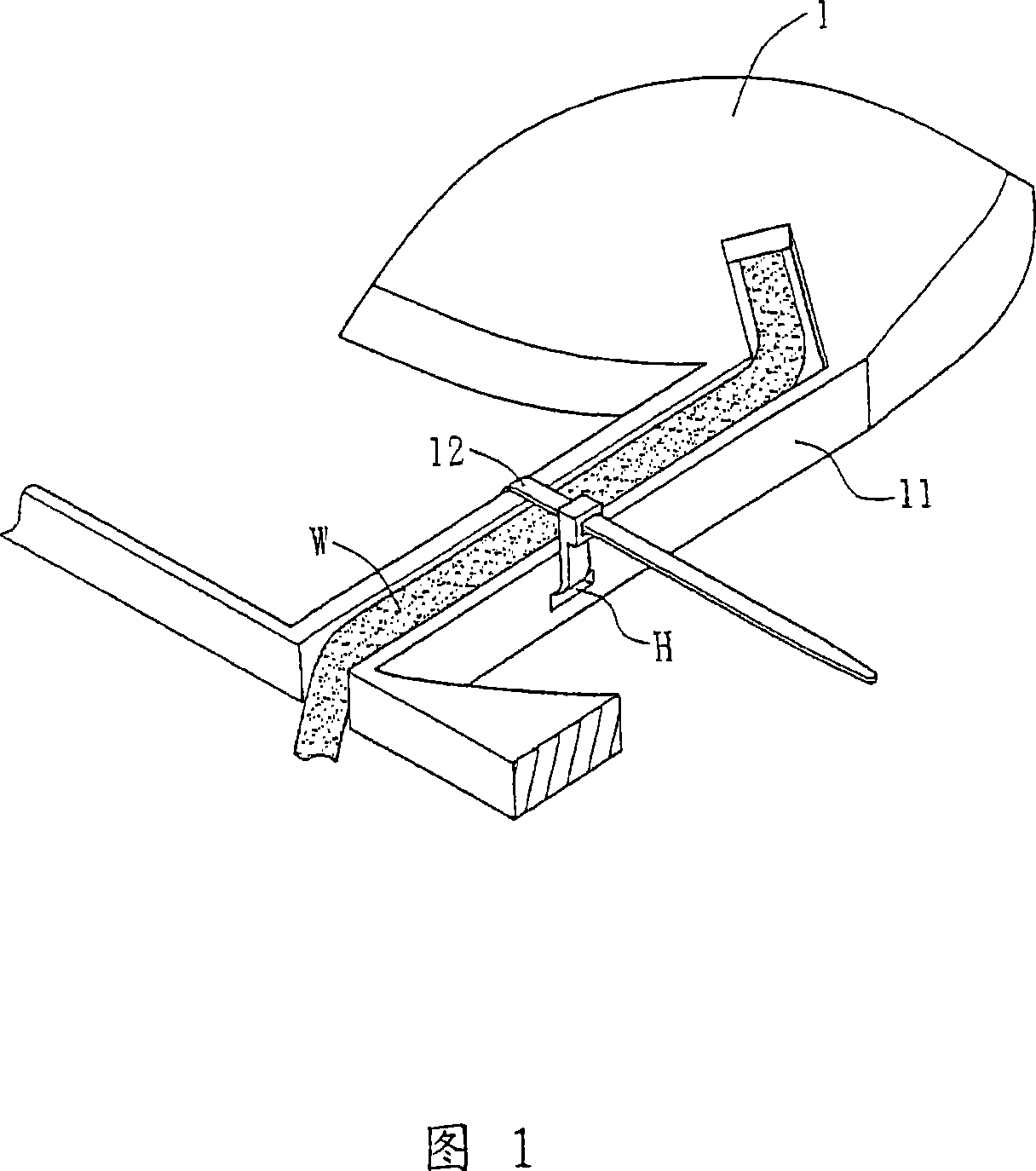
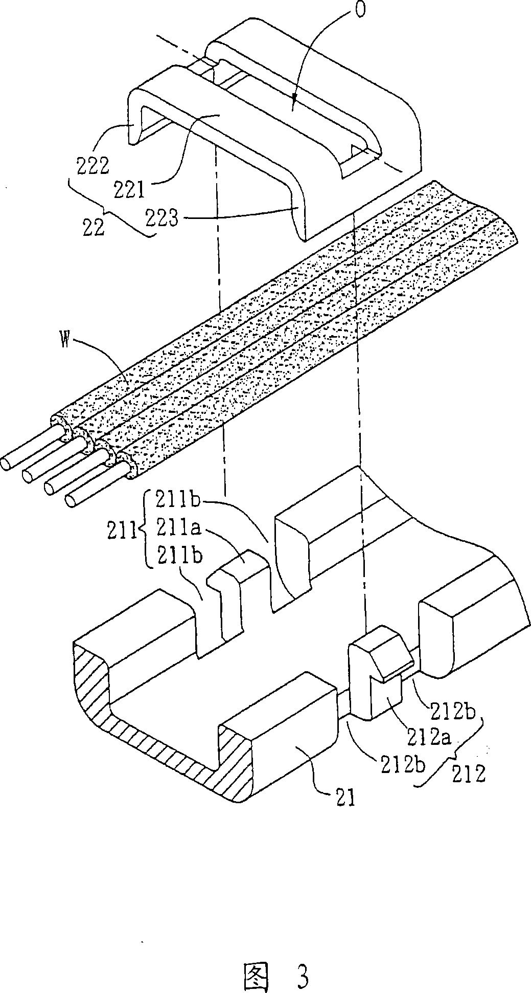
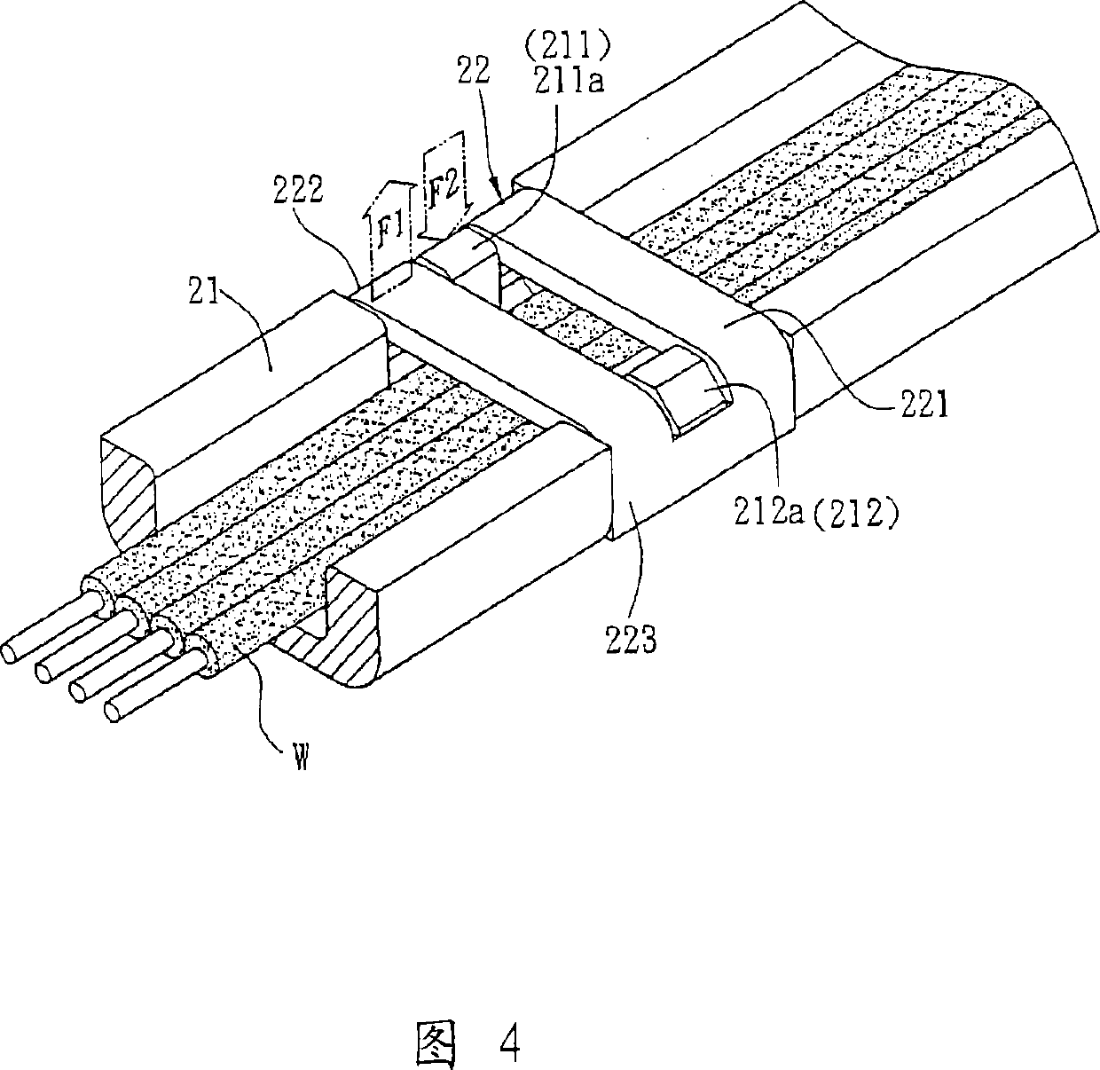
[0026] Please refer to Fig. 2, Fig. 3 and Fig. 4 at the same time, wherein Fig. 3 is an exploded and enlarged view of the wire groove and wire fixing element in Fig. 2, and Fig. 4 is a combination diagram of the wire groove and wire fixing element in Fig. 3 . The fan frame 2 of the preferred embodiment of the present invention includes at least one wire slot 21 and at least one wire fixing element 22 . The wire W is accommodated in the wire groove 21 and tightly fixed by the wire fixing element 22 . The fan frame 2 is, for example, an axial-flow fan frame or a centrifugal fan frame. This embodiment takes an axial-flow fan frame as an example for illustration.

[0027] At least two fixing portions 211 , 212 are correspondingly provided on the outer edge of the trunking 21 ...


PUM


Abstract

The invention discloses a fan frame which comprises at least one wire slot and at least one wire material fixing element. The wire slot is used for holding at least one wire material; the wire slot is provided with at least two fixed parts. The wire material fixed element is provided with a retaining part and at least two fixed arms; the fixed arms are respectively arranged at the two opposite sides of the retaining part; the retaining part covers the wire slot; the fixed arms and the fixed part are mutually and correspondingly clamped, hooked or embedded.

Description

technical field [0001] The invention relates to a fan frame. Background technique [0002] Because fans have the advantages of low cost and mature technology, they have been widely used as cooling devices for various electrical appliances. However, in the fan structure, the wires connected to the motor are often loosened due to the vibration when the fan is running, or the wires are pulled when the fan is installed, and the wires are broken and damaged, resulting in a short circuit. [0003] Please refer to FIG. 1 , in the prior art, a band 12 is used to match the hole H on the fan frame 1 to fix the wire W in the wire groove 11 . However, in the prior art, additional processing is required to form the perforated hole H on the wire slot 11 , and cutting off the excess length of the strap 12 needs to be done manually, thus resulting in an increase in the overall cost. [0004] In addition, when the wire rod W is to be overhauled or reworked, the band 12 must be cut off befo...

Claims


Application Information

Patent Timeline
Patent Type & Authority Patents(China)
IPC IPC(8): F04D29/52
Inventor 洪子钧林士凯陈英琦
Owner DELTA ELECTRONICS INC
Why Eureka
Try Eureka