
Damping ratio adjustable tuning quality damper

A tuning quality and adjustable technology, applied in the direction of shock absorber, solid shock absorber, shock absorber, etc., can solve the problems of prone to sideways swing, high price of damper, seal damage, etc., to achieve optimal damping ratio, The effect of stable system and convenient disassembly and assembly

Active Publication Date: 2009-06-17
尹学军 +1
View PDF1 Cites 66 Cited by
  • Summary
  • Abstract
  • Description
  • Claims
  • Application Information

AI Technical Summary

Problems solved by technology

However, although the existing tuned mass damper can adjust the natural frequency at any time, most of its dampers are small-hole throttling or hydraulic oil piston-type structures, and the damping ratio of the damper is constant. Replace the damper. In addition, the seal of the damper is damaged quickly under the condition of reciprocating vibration. After the seal is damaged, the pressure difference of the damping chamber cannot maintain the original design, and the damping force drops, so it must be replaced. The price of the damper is very high, and the solution is to rely on replacement. Such problems are bound to cause great waste
In addition, the horizontal stiffness of existing tuned mass dampers is generally poor, and they are prone to lateral swaying. Therefore, a guide device is required to realize vertical vibration. mass damper
Once the cooperation between the guide device and the vibrating part is not smooth, the performance of this type of tuned mass damper will be greatly affected, so regular inspection and maintenance must be performed, which is very inconvenient

Method used


Image

  • Damping ratio adjustable tuning quality damper
  • Damping ratio adjustable tuning quality damper
  • Damping ratio adjustable tuning quality damper

Examples


Embodiment 1

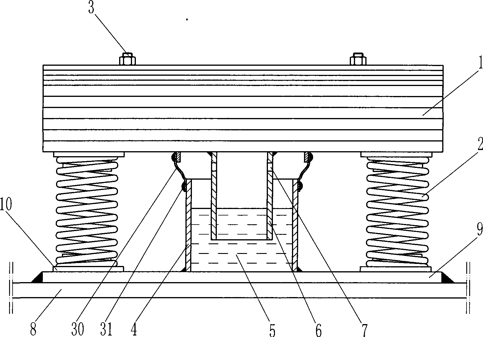
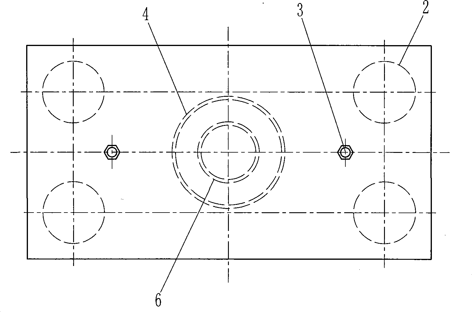
[0029] like figure 1 , figure 2 The tuned mass shock absorber with adjustable damping ratio of the present invention includes a plurality of tuning masses 1, a base 9, four springs 2 and a damper, wherein the spring 2 adopts a helical steel spring, and in order to facilitate the positioning of the spring, the base 9 and the positioning seat 10 are welded on the adjacent mass block of the spring. The damper is an adhesive damper composed of a damping cylinder 4, an adhesive damping fluid 5 (silicon oil here) and a piston 6. The damping cylinder 4 is welded on the base 9, and the adhesive damping fluid 5 is housed in the cylinder. The piston 6 is tubular, its lower end is immersed in the adhesive damping fluid 5, and the upper end of the piston 6 is directly welded to the adjacent tuning mass above it. In order to facilitate the adjustment of the natural frequency of the vibration damping system of the present invention, the tuning mass 1 is combined with multiple steel plate...

Embodiment 2

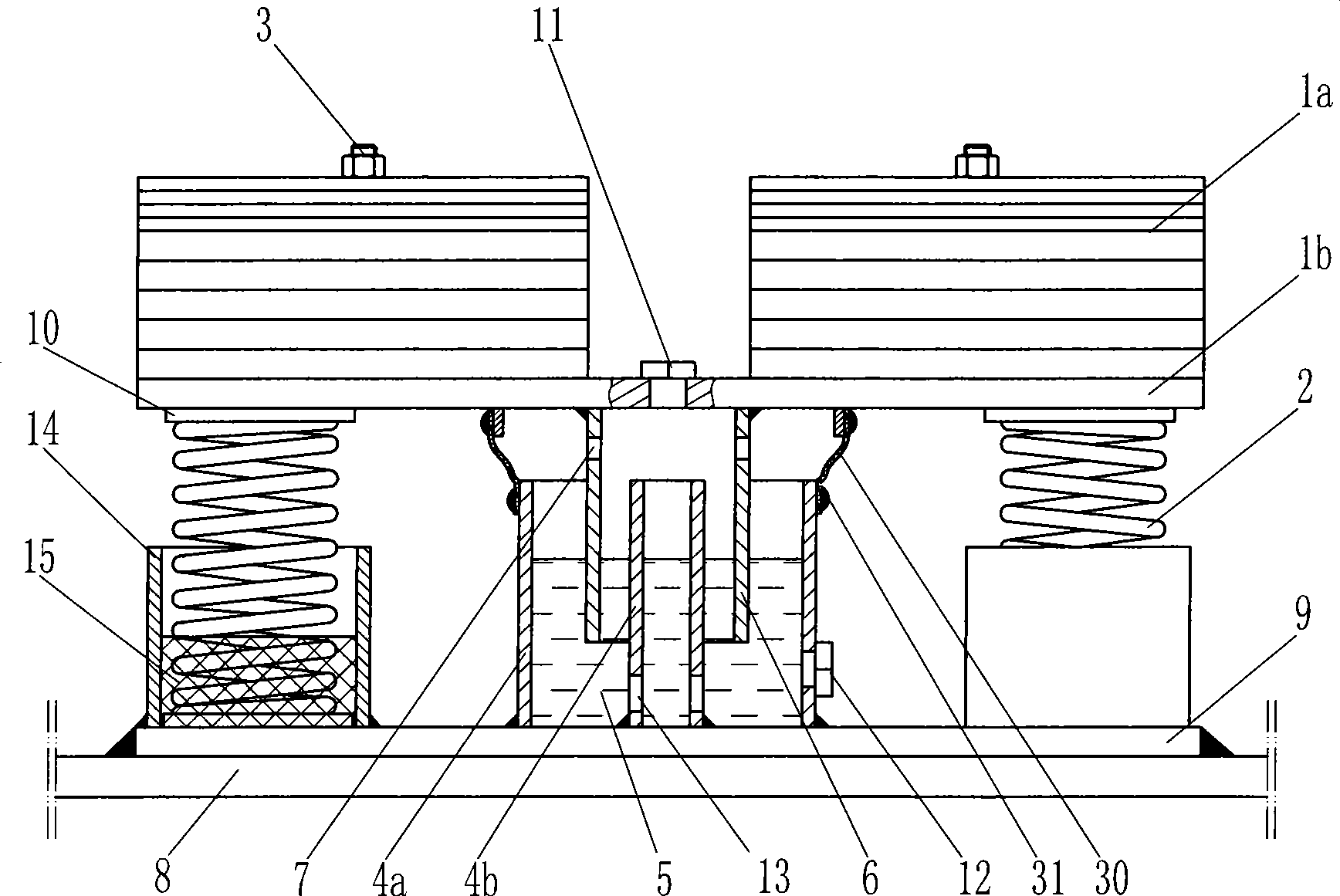
[0034] like image 3 As shown, the difference from the first embodiment is that the tuning mass is arranged in two parts, including the main mass 1b and the adjustment mass 1a symmetrically arranged above the main mass 1b. In order to adjust the damping ratio of the damper conveniently, a damping adjustment device is also provided for the adhesive damper used in the present invention, and the damping adjustment device includes a filling hole and a plug 11 arranged on the main mass 1b and a The drain hole and the plug 12 at the bottom of the damping cylinder 4a. By opening the plug and adding viscous damping fluid or discharging part of the viscous damping fluid, the actual working area of ​​the piston can be changed, thereby achieving the purpose of changing the damping ratio of the damper. A sub-cylinder 4b is added inside the damping cylinder 4a, and the piston 7 cooperates with the damping cylinder 4a and the sub-cylinder 4b at the same time, so as to ensure that the visco...

Embodiment 3

[0038] like Figure 4 , Figure 5 As shown, the difference from Embodiment 1 is that, in order to facilitate the adjustment of the damping ratio of the damper, a damping adjustment device is also provided for the adhesive damper used in the present invention, and the damping adjustment device includes a damping adjustment device arranged on the upper part of the damping cylinder 4a The filling hole and the plug 11 and the drain hole and the plug 12 arranged at the lower part of the damping cylinder 4a can change the actual working area of ​​the piston by adding the sticky damping liquid or discharging part of the sticky damping liquid after opening the plug, so that To achieve the purpose of changing the damping ratio of the damper. In order to facilitate accurate adjustment of the natural frequency of the tuned mass shock absorber with adjustable damping ratio of the present invention, a stiffness adjustment device is also provided at the lower end of the spring 2, and the s...


PUM


Abstract

The invention specifically relates to a mass tuned vibration reducer used for regulating the subsidence ratio of the vibration of the related structures. The mass tuned vibration reducer comprises a mass block, a spring, a damper and a base, and is characterized in that the damper is an adhesion-type damper formed by a damping cylinder, adhesive damping fluid and a piston, wherein, the piston and the adhesive damping fluid are arranged in the damping cylinder, and at least part of the piston is immerged into the adhesive damping fluid. The mass tuned vibration reducer adopts the adhesion-type damper formed by the adhesive damping fluid and the piston and can provide three dimensional damping, so as to effectively prevent side tumbling and ensure the vibration reducer realizes smooth actions; vibration mass is not needed to be provided with a special guide device, so that the mass tuned vibration reducer has reliable work and higher cost performance, and basically needs no maintenance. Meanwhile, the mass tuned vibration reducer realizes the aim of regulating the natural frequency and the subsidence ratio at any time, thus better exerting the vibration absorption performance of the mass tuned vibration reducer, ensuring stableness and safety of the pedestrians and vehicles on the large-span bridge and the thin and high building, contributing to prolonging the service lives of the thin and high building and the bridge, and having remarkable economic and social benefits.

Description

technical field [0001] The invention belongs to the technical field of vibration reduction of civil engineering structures, and in particular relates to a tuned mass damper for controlling the vibration of airport boarding bridges, long-span pedestrian bridges, port trestles, high-rise buildings and related structures. Background technique [0002] With the development of urban construction, the urban transportation network is becoming more and more developed. Various long-span airport boarding bridges, pedestrian bridges, port trestles and other bridge structures have been widely used, bringing great convenience to people's travel. . However, although the strength and stiffness of this type of bridge are relatively easy to meet the design requirements, the frequency of its vertical vibration is generally relatively low (for example, the vertical frequency of a long-span pedestrian bridge is usually only about 2 Hz). Resonance is prone to occur under the action of dynamic l...

Claims


Application Information

Patent Timeline
IPC IPC(8): E04B1/98F16F9/30F16F9/32
CPCF16F7/116F16F9/103F16F2222/08F16F2222/12
Inventor 尹学军
Owner 尹学军
Learn More