Dismantling method of bottom section of blast furnace
A technology for blast furnaces and blast furnaces, which is applied to blast furnaces, blast furnace details, blast furnace parts, etc., can solve the problems of longer demolition period, shortened demolition period, and inability to install, achieving the effect of shortening the demolition period
Active Publication Date: 2009-06-03
NIPPON STEEL & SUMIKIN ENG CO LTD
View PDF2 Cites 4 Cited by
- Summary
- Abstract
- Description
- Claims
- Application Information
AI Technical Summary
Problems solved by technology
Therefore, in order to remove the furnace shell around the furnace body and move out the cured material layer in the blast furnace together with the refractory bricks at the bottom of the furnace, a very large amount of work is required, so the entire demolition period may not be shortened.
[0005] In addition, the above-mentioned dismantling method also has the following problem: when removing the furnace bottom, since the furnace shell of the blast furnace bottom (the furnace shell below the furnace body cutting position) and the furnace floor must be cut and separated, the blast furnace furnace cannot be used. The bottom furnace shell is suspended or lifted by a jack. Therefore, the slide rails or rolling parts for pulling the furnace bottom cannot be placed under the cut furnace bottom refractory bricks, which will lead to the pulling operation of the blast furnace bottom. unstable
[0009] That is, the above-mentioned dismantling method has the following problems: because the separation gap will take into account the "deformation of the furnace body", in order to ensure a sufficient separation gap, the bottom of the furnace must be lifted with a jack and a bracket for lifting must be installed. etc., these tasks make the work intensity increase
[0014] Therefore, when dismantling a large blast furnace, the equipment or equipment required for the dismantling work must be large, and the dismantling method is complicated, resulting in a long time for dismantling
That is, for the dismantling of a large blast furnace, from the current situation, there is no more appropriate method to dismantle the furnace body in a short period of time
Method used
View moreImage
Smart ImageViewing Examples
Examples
Embodiment 1
[0210] Example 1: No measure A, no measure B, no measure C. ...no action
Embodiment 2
[0211] Example 2: implement measure A, no measure B, no measure C. ...only measure A
Embodiment 3
[0212] Example 3: no measure A, no measure B, no measure C. ...only measure B
Login to View More PUM
 Abstract
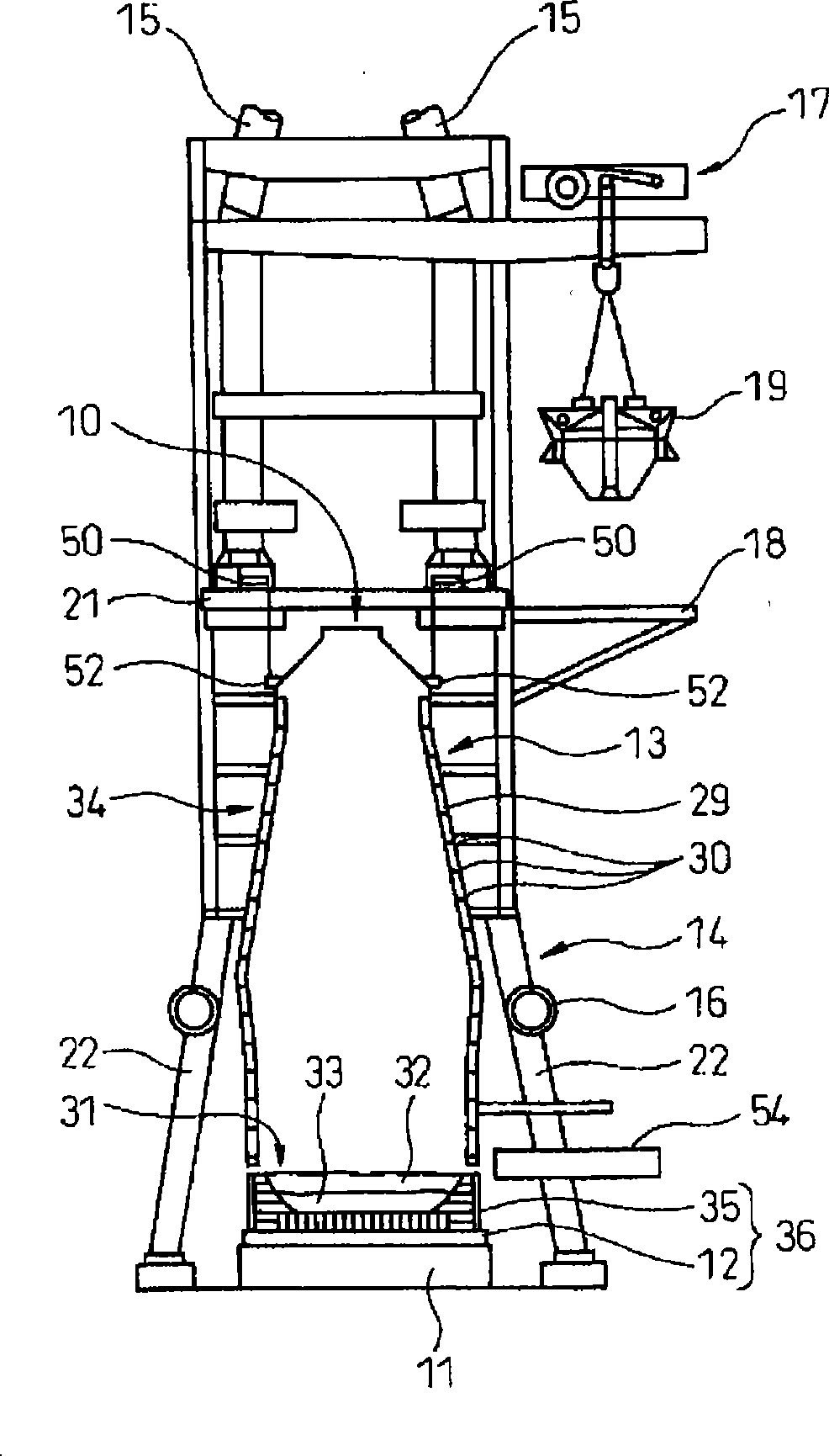
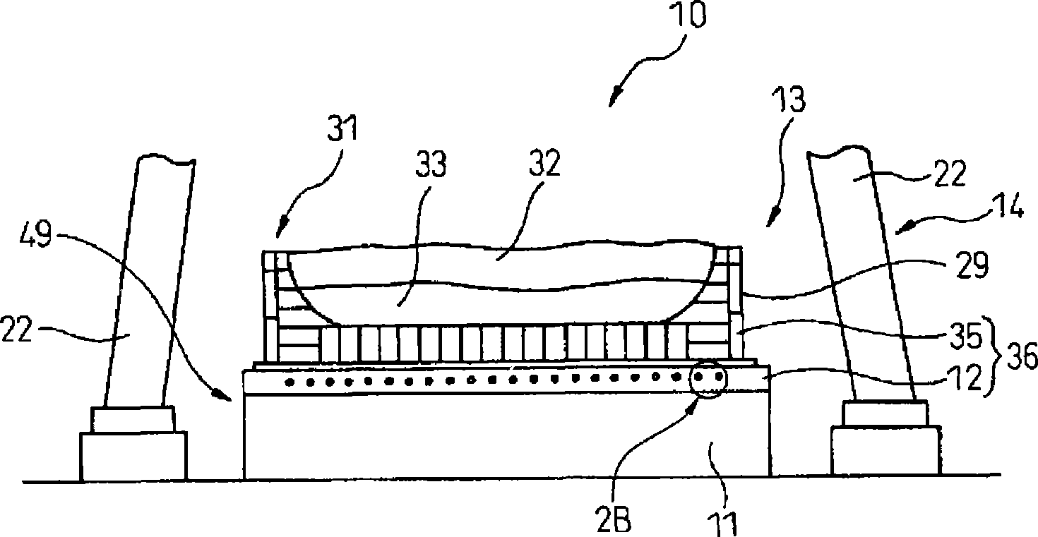
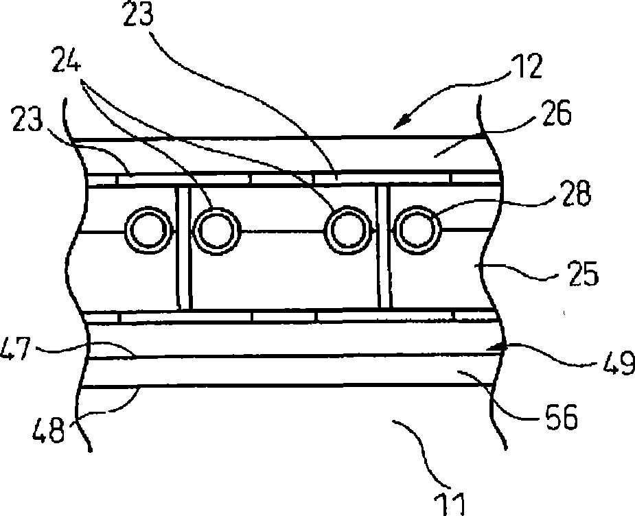
The dismantling method comprises steps 1-8. Step 1: a plurality of cutting sections are set in the direction parallel with the drawing direction on a horizontal cutting plane set in the foundation concrete at the bottom of a blast furnace. Step 2: a horizontal hole is bored in parallel with the drawing direction in the foundation concrete on the boundary of the cutting sections. Step 3: the foundation concrete in the cutting section is cut along the upper and lower horizontal planes by inserting a wire into adjoining horizontal holes. Step 4: an air gap portion is formed by discharging the foundation concrete between the upper and lower horizontal cutting planes. Step 5: a lateral movement member for carrying out the furnace bottom section is arranged in the air gap portion. Step 6: a furnace body load supporting member is provided in the gap between the upper surface of the lateral movement member and the upper horizontal cutting plane. Step 7: a lateral movement means equipped with the lateral movement member and the furnace body load supporting member is arranged over the entire region of a horizontal cutting portion by repeating the steps 2-6 or steps 3-6. Step 8: an upper mantel is separated from the furnace bottom, hoisted and carried out by imparting a horizontal force.
Description
technical field [0001] The invention relates to a method for dismantling the bottom of a blast furnace, which is used for dismantling the bottom of the blast furnace in a short period of time during the overhaul of the blast furnace. Background technique [0002] In the process of overhauling the blast furnace, the bottom of the blast furnace will be dismantled and moved outside the blast furnace system. When moving, the existing technology is to discharge the molten iron and slag remaining in the bottom of the blast furnace as much as possible, and then carry out Demolition job. For such dismantling work, some methods of shortening the dismantling period have been proposed (for example, refer to Patent Documents 1 and 2). [0003] Patent Document 1 discloses a method for dismantling the bottom of a blast furnace: that is, when the solidified layer and the refractory brick layer remaining on the bottom of the blast furnace are moved to the outside of the blast furnace after...
Claims
Login to View More Application Information
Patent Timeline
 IPC IPC(8): C21B7/00
CPCC21B7/02F27B1/14C21B7/00
Inventor 高崎洋滨田孝司须藤雄二
Owner NIPPON STEEL & SUMIKIN ENG CO LTD
Features
- R&D
- Intellectual Property
- Life Sciences
- Materials
- Tech Scout
- Unparalleled Data Quality
- Higher Quality Content
- 60% Fewer Hallucinations
Learn More Browse by: Latest US Patents, China's latest patents, Technical Efficacy Thesaurus, Application Domain, Technology Topic, Popular Technical Reports.
© 2025 PatSnap. All rights reserved.Legal|Privacy policy|Modern Slavery Act Transparency Statement|Sitemap|About US| Contact US: help@patsnap.com


