
Array substrate and method for manufacturing the same

A technology for array substrates and substrates, which is used in semiconductor/solid-state device manufacturing, optics, instruments, etc., and can solve the problems of proportional increase in line thickness and other issues.

Active Publication Date: 2009-06-03
SAMSUNG DISPLAY CO LTD
View PDF2 Cites 11 Cited by
  • Summary
  • Abstract
  • Description
  • Claims
  • Application Information

AI Technical Summary

Problems solved by technology

Moreover, even if low-resistance lines are adapted to array substrates, line thicknesses still need to be increased in a proportional progression

Method used


Image

  • Array substrate and method for manufacturing the same
  • Array substrate and method for manufacturing the same
  • Array substrate and method for manufacturing the same

Examples


Embodiment Construction

[0019] The present invention will be described more fully hereinafter with reference to the accompanying drawings, in which embodiments of the invention are shown. However, this invention may be embodied in many different forms and should not be construed as limited to the embodiments set forth herein. Rather, these embodiments are provided so that this disclosure will be thorough and complete, and will fully convey the scope of the invention to those skilled in the art. In the drawings, the size and relative sizes of layers and regions may be exaggerated for clarity.

[0020] It will be understood that when an element or layer is referred to as being "on," "connected to," or "bonded to" another element or layer, it can be directly on , connected or joined to another element or layer, or the presence of an intervening element or layer. In contrast, when an element is referred to as being "directly on," "directly connected to" or "directly joined to" another element or layer,...


PUM


Abstract

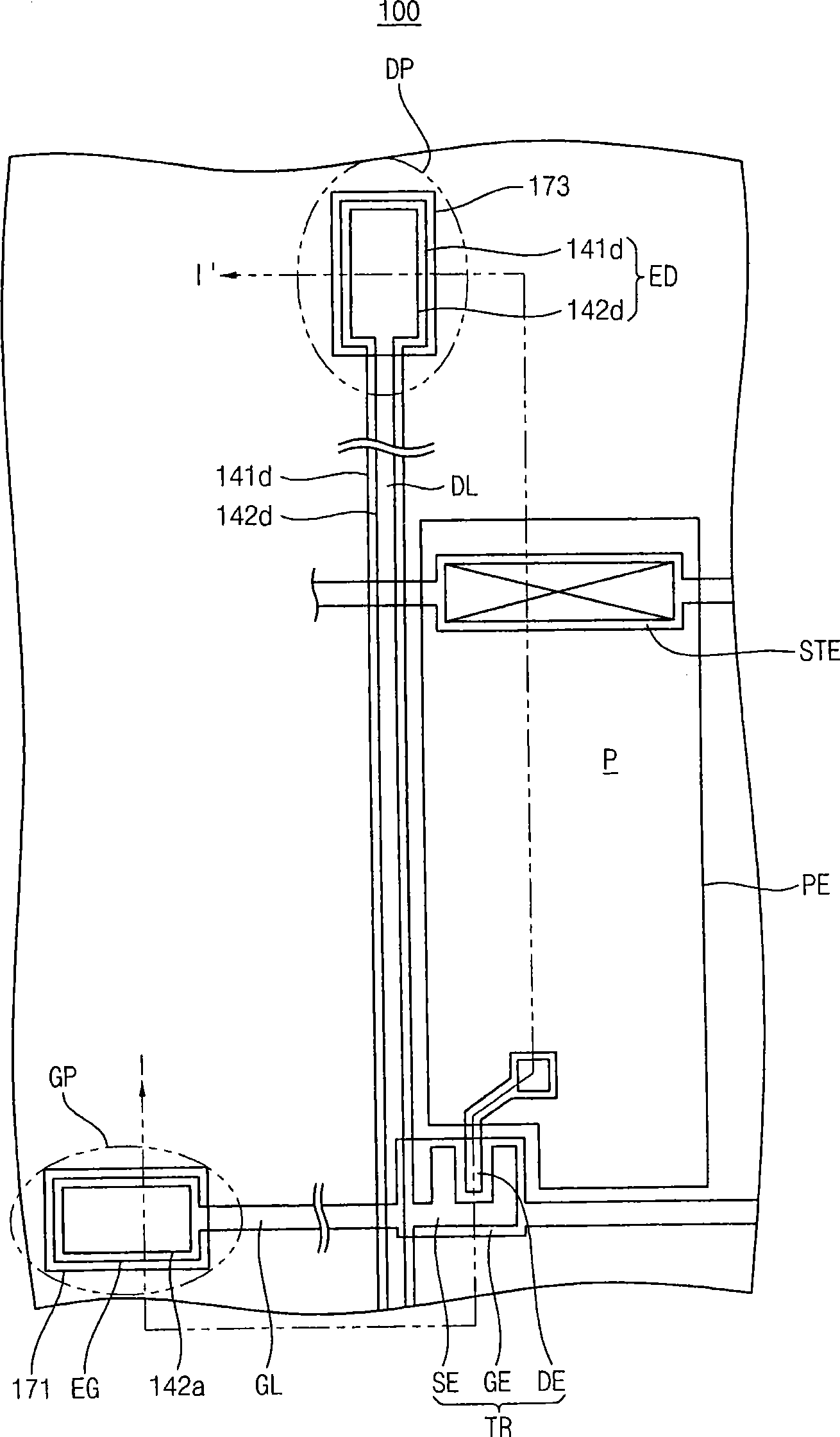
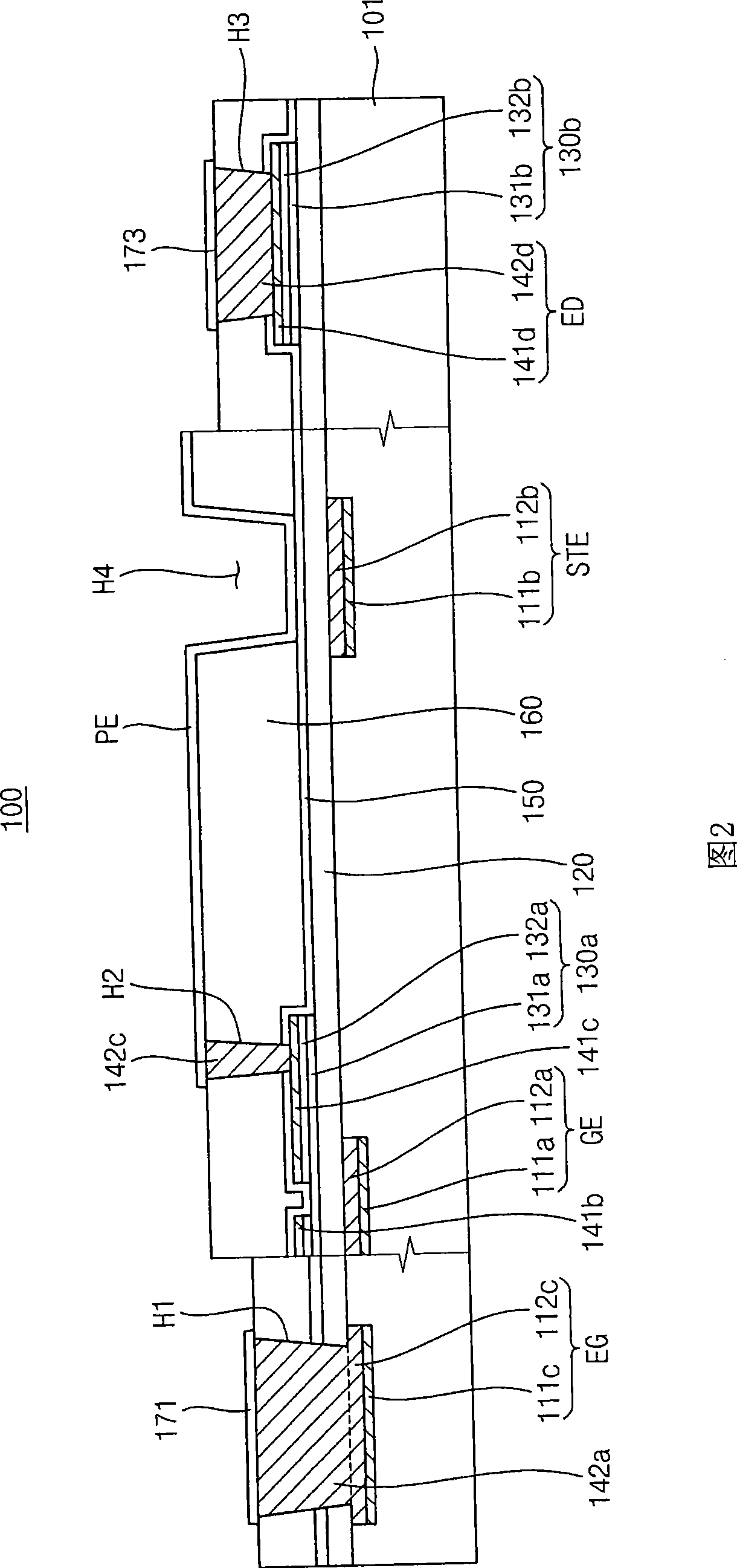
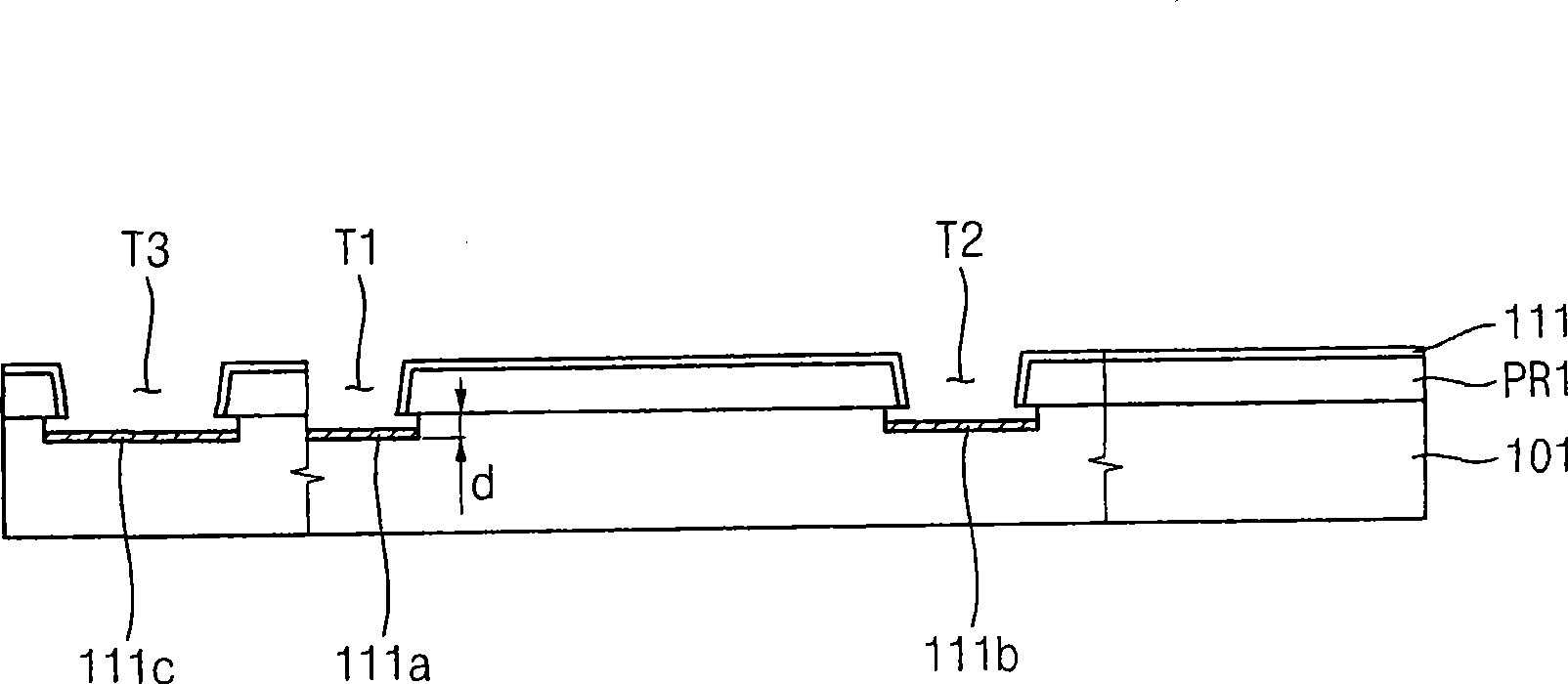
The invention provides a array substrate, wherein a gate line includes a first seed layer formed on a base substrate and a first metal layer formed on the first seed layer. A first insulation layer is formed on the base substrate. A second insulation layer is formed on the base substrate. Here, a line trench is formed through the second insulation layer in a direction crossing the gate line. A data line includes a second seed layer formed below the line trench and a second metal layer formed in the line trench. A pixel electrode is formed in a pixel area of the base substrate. Therefore, a trench of a predetermined depth is formed using an insulation layer and a metal layer is formed through a plating method, so that a metal line having a sufficient thickness may be formed. The invention also provides a method for manufacturing the array substrate.

Description

technical field [0001] The invention relates to an array substrate and a manufacturing method of the array substrate. More specifically, the present invention relates to an array substrate capable of reducing wire resistance and a method for manufacturing the array substrate. Background technique [0002] Generally, a liquid crystal display (LCD) device includes an array substrate (or thin film transistor (TFT) substrate), an opposite substrate, and a liquid crystal layer formed between the array substrate and the opposite substrate. The array substrate includes a plurality of gate lines, a plurality of data lines crossing the gate lines, switching elements electrically connected to the gate lines and the data lines, and pixel electrodes electrically connected to the switching elements. [0003] Since a display device may have a large size and high resolution, it is possible to increase resistance-capacitance delay, hereinafter referred to as RC delay, in metal lines formed...

Claims


Application Information

Patent Timeline
IPC IPC(8): H01L27/12H01L23/522H01L21/84H01L21/768
CPCG02F1/13458H01L27/1288G02F2001/136295H01L27/1218G02F1/136286H01L27/1214H01L27/124G02F1/136295G02F1/136
Inventor 金彰洙宁洪龙金俸均朴弘植金时烈郑敞午金湘甲尹在亨李禹根裴良浩尹弼相郑钟铉洪瑄英金己园李炳珍李永旭金钟仁金炳范徐南锡
Owner SAMSUNG DISPLAY CO LTD
Learn More