
Cast-in-place support for long cantilever No. 0 block of cable-stayed bridge with tower beam consolidation and putting up method

A technology of long and cantilevered cable-stayed bridges, applied in bridge construction, bridges, buildings, etc., can solve the problems of low safety factor, difficult construction, high cost, etc., and achieve the effects of clear force, avoiding safety risks, and easy operation

Inactive Publication Date: 2009-06-03
THE 8TH GRP OF CHINA RAILWAY 1ST ENG CO LTD
View PDF0 Cites 11 Cited by
  • Summary
  • Abstract
  • Description
  • Claims
  • Application Information

AI Technical Summary

Problems solved by technology

When the bottom surface of the cable-stayed bridge body is water or the distance from the ground is high, it is not only difficult to construct and costly to use full-floor scaffolding, but also has a low safety factor.
However, if other stiff corbels are used, and there is no temporary cable system support, it is difficult to control the stiffness of the support. In addition, the connection between the support and the tower body is usually welded, which has great potential safety hazards. It is also difficult to deal with the embedded steel plate in the later stage

Method used


Image

  • Cast-in-place support for long cantilever No. 0 block of cable-stayed bridge with tower beam consolidation and putting up method
  • Cast-in-place support for long cantilever No. 0 block of cable-stayed bridge with tower beam consolidation and putting up method
  • Cast-in-place support for long cantilever No. 0 block of cable-stayed bridge with tower beam consolidation and putting up method

Examples


Embodiment Construction

[0028] Below in conjunction with accompanying drawing, process of the present utility model is further described by engineering example.

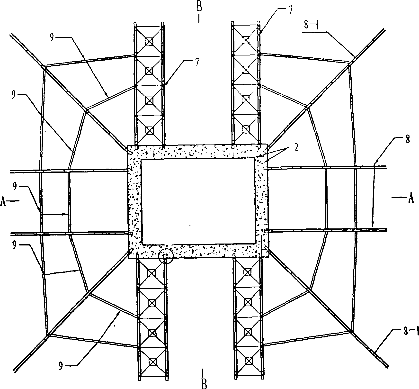
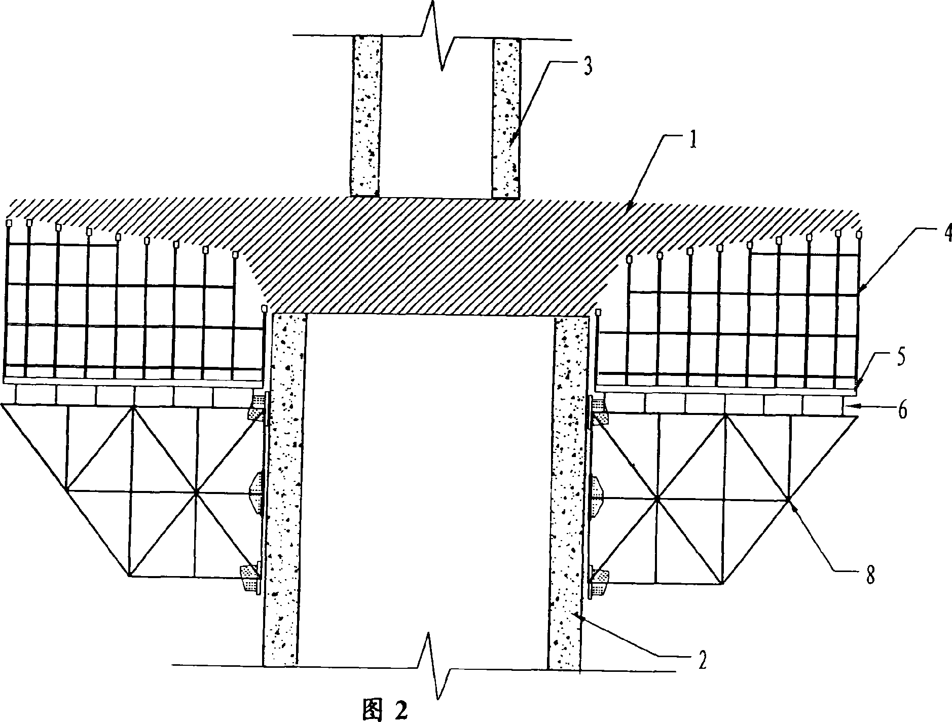
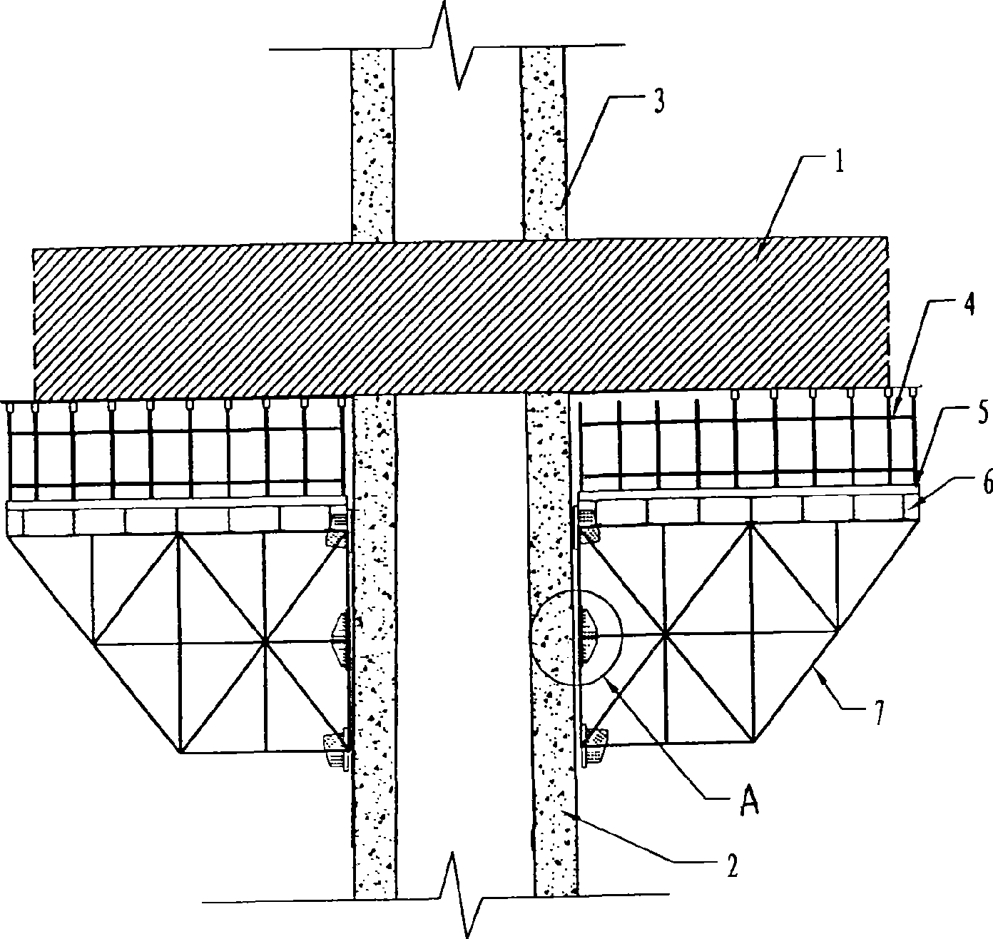
[0029] see figure 1 ,figure 2, image 3 and Figure 4 , a kind of cast-in-situ support of long cantilever 0# block 1 of a tower beam consolidation cable-stayed bridge according to the present invention comprises a detachable truss frame connected to the upper part of the lower tower column 2, and a detachable truss frame laid on the upper part of the lower tower column The I-beam distribution beam 6 above, the sleeper 5 laid on the I-beam distribution beam and the bowl fastener support 4 built on the sleeper;

[0030] The detachable truss frame includes four sets of double truss groups 7 symmetrically connected to both sides of the lower tower column along the direction of the bridge, and four single truss groups symmetrically connected to both sides of the lower tower column along the direction of the bridge. The truss 8 and four obliqu...


PUM


Abstract

The invention relates to a cast-in-place support for the long cantilever No. 0 block of a cable-stayed bridge with tower beam consolidation, which comprises a reassembling type truss girder falsework, an I-shaped steel distributive girder, a sleeper and a bowl-fastening piece support, wherein the reassembling type truss girder falsework is connected at the upper part of the a lower pylon column; the I-shaped steel distributive girder is laid on the reassembling type truss girder falsework; the sleeper is laid on the I-shaped steel distributive girder, and the bowl-fastening piece support is built on the sleeper. The cast-in-place support is characterized in that reassembling type truss girder falsework is formed to be an inverted trapezoid through the connection of four groups of double-beam truss group, four single-beam trusses and four oblique angled single-beam trusses. The method for putting up the cast-in-place support comprises the following steps: pre-burying a bolt sleeve; mounting a special angle iron and a special gusset plate; putting up the reassembling type truss girder falsework; laying the I-shaped steel distributive girder; laying the sleeper and putting up the bowl-fastening piece support. The invention has the advantages of long cantilever, strong load bearing capability, big stiffness, clear stress and simple and easy operation, and safety risks caused by welding defects are avoided.

Description

technical field [0001] The invention relates to a building support and a construction method thereof, in particular to a cast-in-situ support of the long cantilever 0# block of a tower-beam consolidated cable-stayed bridge and a construction method thereof. Background technique [0002] The long cantilever block 0# of the tower-girder consolidated cable-stayed bridge is the intersection point of the side-span beam, mid-span beam, upper tower column and lower tower column. It plays an important role and directly affects the construction of subsequent parts of the project. The cast-in-place support structure of the long cantilever 0# block has a significant impact on the quality of the concrete. At present, the cast-in-place construction of the long cantilever 0# block usually adopts full floor scaffolding or rigid corbels. When the 0# block of the long cantilever is not high from the ground and there is a scaffolding site, a full floor scaffolding is often used. When const...

Claims


Application Information

Patent Timeline
IPC IPC(8): E01D21/10
Inventor 罗磊任历文张开聪李定达周成彬黄基富杨名王诗黔
Owner THE 8TH GRP OF CHINA RAILWAY 1ST ENG CO LTD
Learn More