Drive system for hybrid power automobile air conditioner compressor and hydraulic pump

A technology for hybrid electric vehicles and air-conditioning compressors, which is applied to the arrangement of multiple different prime movers of power units, general power units, and pneumatic power units, etc. Energy saving goals and other issues to achieve the effect of eliminating mechanical loads and avoiding interference

Inactive Publication Date: 2009-05-27
CHONGQING UNIV
View PDF4 Cites 20 Cited by
  • Summary
  • Abstract
  • Description
  • Claims
  • Application Information

AI Technical Summary

Problems solved by technology

However, it will inevitably cause difficulties in arranging transmission equipment in a limited space structure and a relative increase in cost, resulting in difficulties in installation and maintenance; moreover, the transmission process will cause interference and drive additional loads to run, which will inevitably result in a reduction in energy conversion efficiency. , which is not conducive to the realization of the energy-saving goal of hybrid electric vehicles
[0006] Therefore, need a kind of hybrid electric vehicle air-conditioning compressor and hydraulic pump drive system, can avoid engine and electric motor to the interference that produces when driving air-conditioning compressor and hydraulic pump, can solve pure electric working condition (engine stoppage) in hybrid electric vehicle ) to drive the hydraulic pump and air-conditioning compressor, avoiding the problems of low energy conversion rate and large energy loss caused by the hydraulic pump and air-conditioning compressor driven by the motor alone, and achieving the purpose of energy saving

Method used


Image

  • Drive system for hybrid power automobile air conditioner compressor and hydraulic pump

Examples


Embodiment Construction

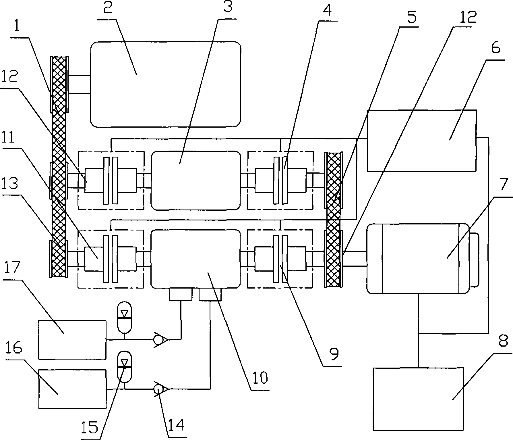
[0021] Accompanying drawing is a structural representation of the present invention, as shown in the figure: the hybrid vehicle air-conditioning compressor of the present embodiment and the hydraulic pump drive system comprise engine 2, accumulator 8 and motor 7, and accumulator 8 is the power supply of motor 7; Drive air-conditioning compressor 3 and hydraulic pump 10 by clutch I 12 and clutch II 11 respectively, electric motor 7 drives air-conditioning compressor 3 and hydraulic pump 10 by clutch III4 and clutch IV9 respectively; In the present embodiment, clutch I 12 and clutch III4 and The air-conditioning compressor 3 is coaxially connected, and the clutch II 11 and clutch IV9 are coaxially connected with the hydraulic pump 10, so that the entire drive system is compact in structure, easy to install and maintain, and reduces energy loss during transmission;

[0022] Also includes controller 6, clutch I 12, clutch II 11, clutch III4 and clutch IV9 are electromagnetic clutch...


PUM


Abstract

The invention discloses an air-conditioner compressor of hybrid vehicle and a hydraulic pump driving system; the air-conditioner compressor includes an engine and an electric motor, wherein, the engine respectively drives the air-conditioner compressor and a hydraulic pump by a clutch I and a clutch II, and the electric motor respectively drives the air-conditioner compressor and the hydraulic pump by a clutch III and a clutch IV; the air-conditioner compressor and the hydraulic pump are respectively driven by the engine and the electric motor through the clutches, and a transmission system is relatively independent, so that the problem of driving the air-conditioner compressor and the hydraulic pump when the engine stops; when in driving, mechanical joint between the engine and the electric motor can be cut off, thus eliminating the mechanical load of the electric motor to the engine, and avoiding the interference caused by that the engine and the electric motor drive the air-conditioner compressor and the hydraulic pump at the same time; therefore, the problems of low energy conversion rate and high energy dissipation which are brought by the air-conditioner compressor and the hydraulic pump are separately driven by the electric motor are avoided, and the aim of energy-saving and emission-reduction is achieved.

Description

technical field [0001] The invention relates to a driving system of an auxiliary equipment of an automobile, in particular to a driving system of an air conditioner compressor and a hydraulic pump of a hybrid electric vehicle. Background technique [0002] Automobile air conditioning and hydraulic power assist or braking systems are indispensable devices for automobiles. The traditional engine-powered vehicle uses the engine to provide the power source, and transmits the power to the car air conditioner and hydraulic pump through the transmission system to complete the corresponding functions, which not only increases the power consumption of the engine, but also increases the pollution to the environment. [0003] With the increasing pressure of energy depletion and environmental protection, hybrid electric vehicles have appeared. Hybrid electric vehicles use fuel-driven and electric-driven driving methods, and coordinate the two driving methods through reasonable control s...

Claims


Application Information

Patent Timeline
IPC IPC(8): B60K6/20B60K6/387B60W10/30B60W10/08
CPCY02T10/92
Inventor 胡建军胡明辉秦大同董小洪胡宏奎
Owner CHONGQING UNIV
Why Eureka
Try Eureka