
A disaster tolerance switching method, system and apparatus

A technology of disaster recovery switching and switching instructions, which is applied in the direction of electrical components, wireless communication, etc., can solve the problems of low accuracy and poor timeliness, and achieve the effect of improving timeliness and accuracy

Active Publication Date: 2009-05-06
CHINA MOBILE GROUP SHANDONG
View PDF0 Cites 28 Cited by
  • Summary
  • Abstract
  • Description
  • Claims
  • Application Information

AI Technical Summary

Problems solved by technology

[0006] In the prior art, the entire process of disaster recovery switchover, including switching the services of the faulty network element to the backup network element, and switching the services from the backup network element back to the network element for fault recovery, etc., is completed by manual operation , has the defects of poor timeliness and low accuracy in implementation

Method used


Image

  • A disaster tolerance switching method, system and apparatus
  • A disaster tolerance switching method, system and apparatus
  • A disaster tolerance switching method, system and apparatus

Examples


Embodiment 1

[0096] see Figure 5 , in this embodiment, base station controller 1 (BSC1) manages base station 1 (BTS1) and base station 2 (BTS2), base station controller 2 (BSC2) manages base station 3 (BTS3), and performs disaster recovery between BSC1 and BSC2 The specific process of switching is as follows:

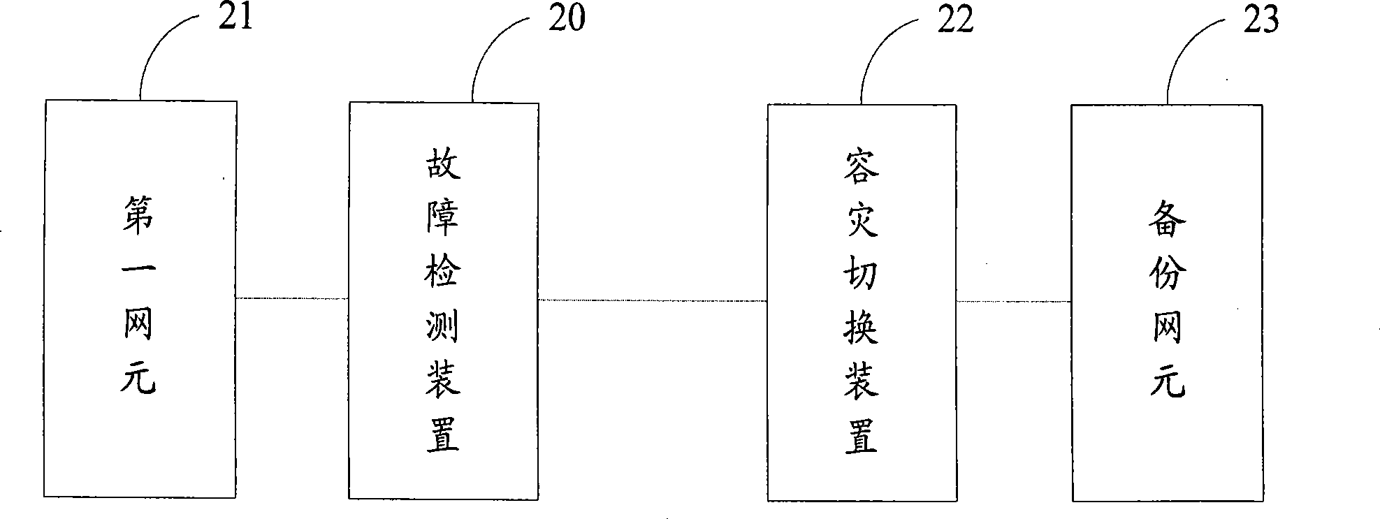
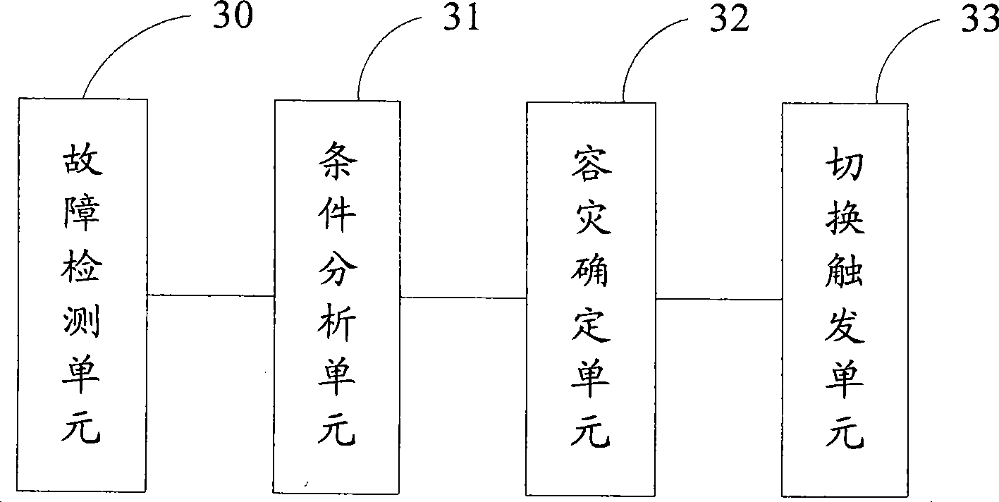
[0097] Step S01: The fault detection device detects the real-time state of BSC1, and records the alarm signal sent by BSC1 and the sending time; every hour, compares the recorded information with the threshold value of the number of alarm signals in the disaster recovery rule base, and finds that If the recorded number of alarm signals issued in the last hour exceeds the threshold value of the number of alarm signals, it is determined that BSC1 has failed;

[0098] Step S02: the fault detection device sends a switching trigger message to the disaster recovery switching device, and the message includes the category information of BSC1 and the related information of BTS1 and BTS2 ma...

Embodiment 2

[0109] see Figure 6 , in the present embodiment, the specific process of carrying out disaster recovery switching between the home location register 1 (HLR1) and the home location register 2 (HLR2) is as follows:

[0110] Step S11: The fault detection device detects the timing status of HLR1, obtains the available storage space parameter information of HLR1 through interaction with HLR1 and records the information; compares the recorded available storage space parameters with the storage space threshold value in the disaster recovery rule base Comparative analysis, if it is found that the available storage space of the record is less than the storage space threshold value, then it is determined that HLR1 is out of order;

[0111] Step S12: the fault detection device sends a switching trigger message to the disaster recovery switching device, and the message includes the category information of BSC1;

[0112] Step S13: The disaster recovery switchover device receives the swit...


PUM


Abstract

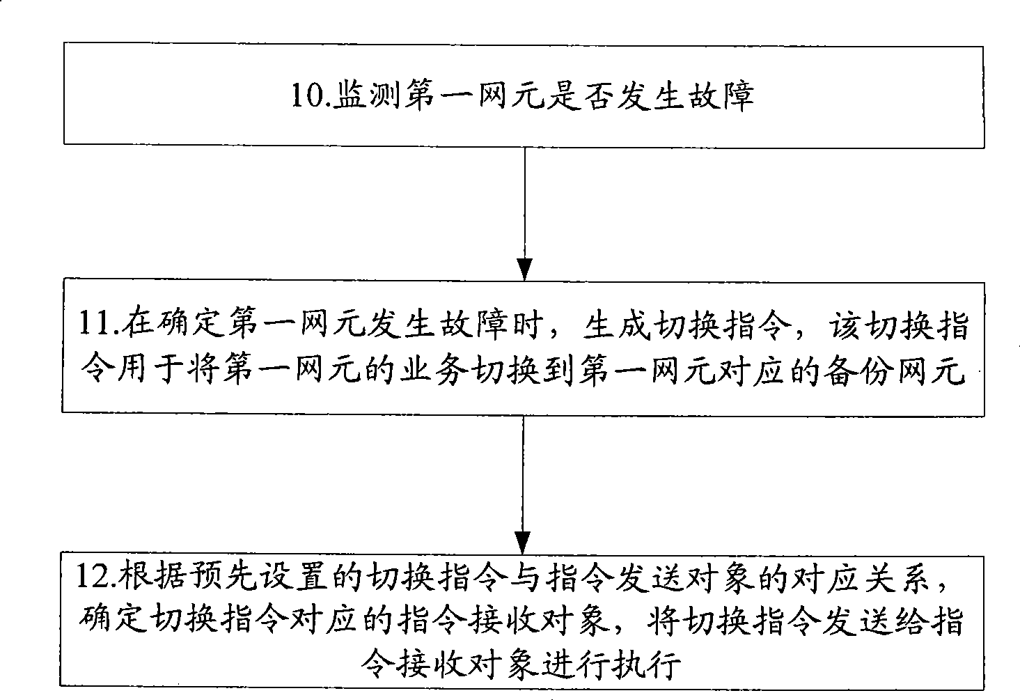
An embodiment of the invention discloses a method for switching disaster recovery, wherein the method comprises the following procedures: monitoring whether a first network element has a failure, generating a switching instruction which is used for switching the service of the first network element to a backup network element corresponding with the first network element when the failure of the first network element is confirmed; and confirming an instruction receiving object corresponding with the switching instruction according to the corresponding relationship between the pre-collocated instruction and the instruction receiving object, and transmitting the switching instruction to the instruction receiving object for executing. The embodiment of the invention also discloses a disaster recovery switching system and device. The timeliness and accuracy in the disaster recovery process can be effectively increased according to the invention.

Description

technical field [0001] The present invention relates to the field of mobile communication, in particular to a disaster recovery switching method, system and device. Background technique [0002] With the popularity of mobile communication networks, users have higher and higher requirements for mobile communication service quality; operators also require that the network can continue to provide services after network nodes fail. In order to improve the operation level, mobile operators must provide users with high-quality, uninterrupted services. Due to human error, equipment failure, natural disasters and other reasons, failures of communication network elements are often inevitable. [0003] In order to provide users with uninterrupted services, a disaster recovery switching is required when a network element fails. Disaster recovery switching refers to switching the services of a faulty network element to other normal network elements, and the normal network element take...

Claims


Application Information

Patent Timeline
IPC IPC(8): H04W88/18H04W36/08
Inventor 孔建坤陈国栋孙艳丽姚进华宋志刚
Owner CHINA MOBILE GROUP SHANDONG
Learn More