
Optical fiber F-P acceleration and pressure sensor and its manufacturing method

A technology of pressure sensor and manufacturing method, applied in the direction of acceleration measurement using inertial force, fluid pressure measurement using optical method, cladding optical fiber, etc., can solve the problem of high temperature sensitivity, unfavorable large-scale manufacturing, and poor repeatability and other issues to achieve the effect of good optical performance

Inactive Publication Date: 2009-05-06
冉曾令
View PDF1 Cites 28 Cited by
  • Summary
  • Abstract
  • Description
  • Claims
  • Application Information

AI Technical Summary

Problems solved by technology

The common disadvantage of these acceleration sensors is that other structures are required to form the acceleration sensor, such as mass blocks, beams or springs, etc., which are large in size and difficult to use in high-temperature environments, and the repeatability of the sensor needs to be improved.
US6921894 discloses a micro-fiber fiber optic accelerometer, which connects the optical fiber and the mass block through a spring, which has the disadvantages of poor repeatability, high temperature sensitivity, unfavorable large-scale manufacturing, and poor optical performance.

Method used


Image

  • Optical fiber F-P acceleration and pressure sensor and its manufacturing method
  • Optical fiber F-P acceleration and pressure sensor and its manufacturing method
  • Optical fiber F-P acceleration and pressure sensor and its manufacturing method

Examples


Embodiment 1

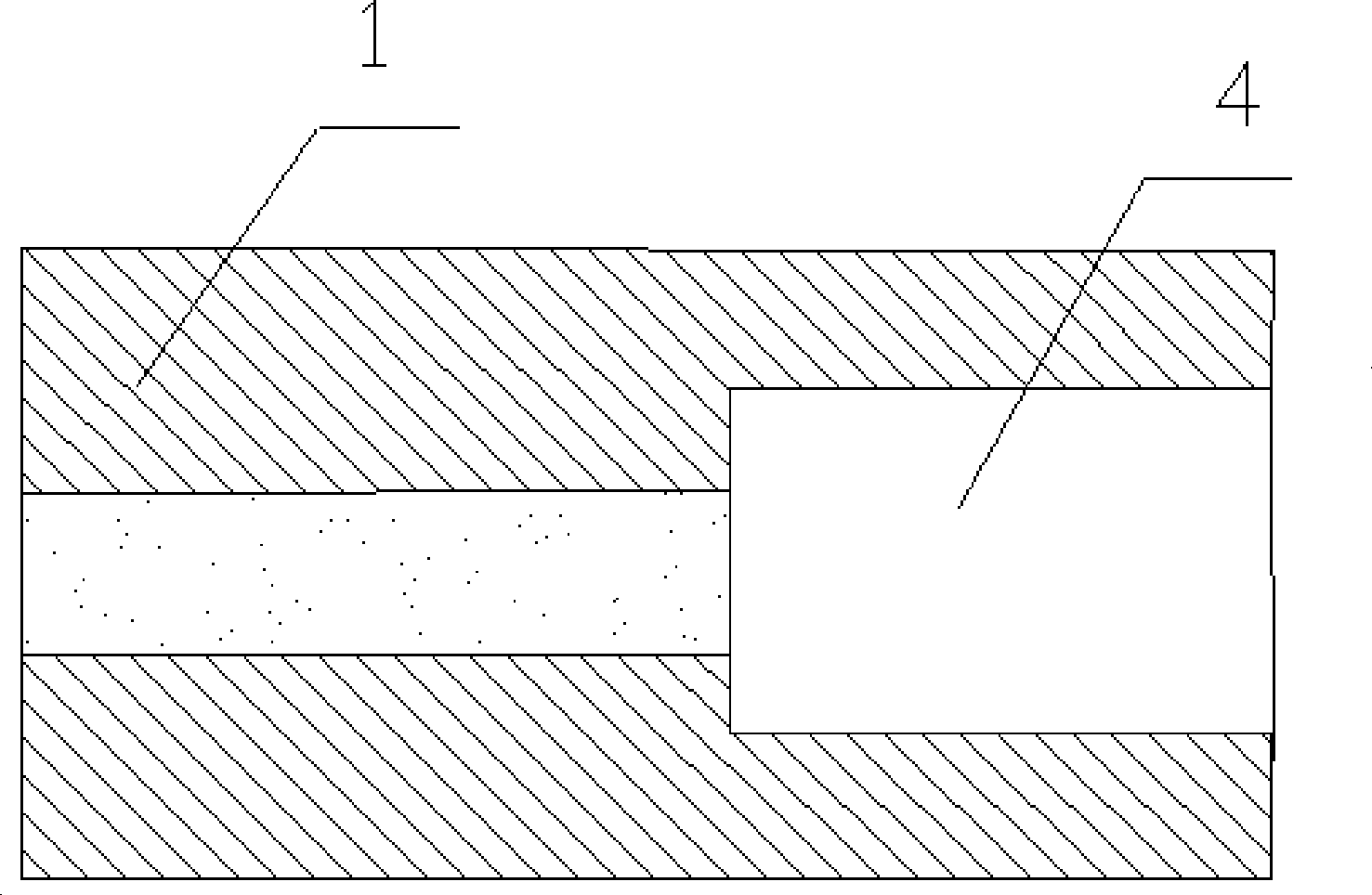
[0029] Step 1, processing a deep 100 micron microgroove 4 with a 157nm ultraviolet laser on the quartz optical fiber 1, such as figure 1 shown;

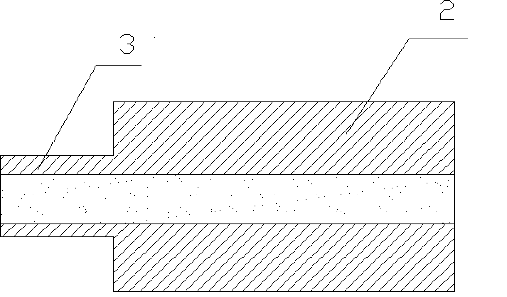
[0030] Step 2, processing the end face of the connected optical fiber 2 with a 157nm ultraviolet laser to process a protrusion 3 with a length of 60 microns, such as figure 2 shown;

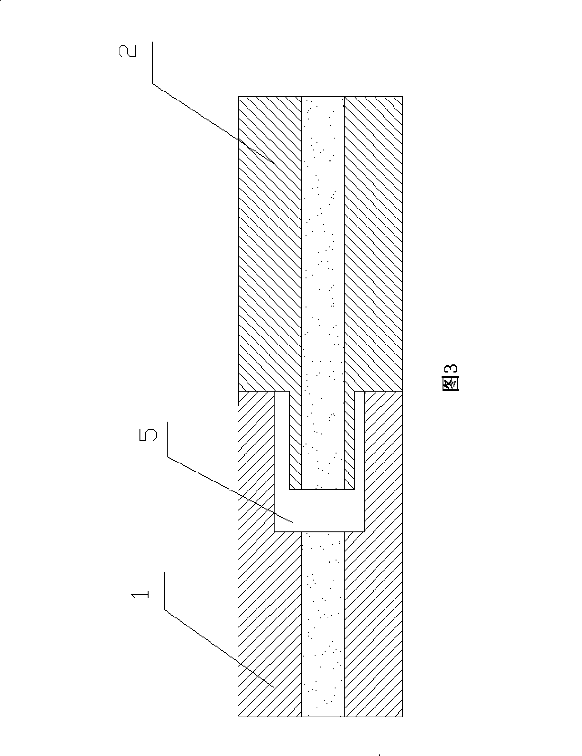
[0031] Step 3. Weld the optical fibers formed in step 1 and step 2 together to form a enamel cavity 5, wherein the end of the connected optical fiber 2 with the protrusion 3 is welded with the end of the optical fiber 1 with the microgroove 4, as shown in Figure 3 ;

[0032] Step 4, cutting the outer end face of the connected optical fiber 2 to form a diaphragm 6, that is, to make the optical fiber Fabac acceleration and pressure sensor with a hard center of mass (protrusion 3) of the present invention, as shown in Figure 4, the sensor's Spectral graph such as Figure 7 shown.

[0033] When in use, when the sensor feels pressure and acceleration, ...

Embodiment 2

[0035] Step 1, processing a microgroove 4 with a depth of 40 microns on the gem fiber 1 with a femtosecond laser;

[0036] Step 2. Weld together with the connected optical fiber 2 to form a Fappaure cavity 5, process a protrusion 3 with laser at the other end of the connected optical fiber 2, and form a diaphragm 6, thus forming a hard mass center (i.e. protrusion 3) Acceleration and pressure sensors, as shown in Figure 5.

Embodiment 3

[0038] Step 1, processing a microgroove 4 with a depth of 100 microns on the optical fiber 1;

[0039] Step 2, processing the end face of the connected optical fiber 2 with a 157nm ultraviolet laser to process a protrusion 3 with a length of 60 microns;

[0040] Step 3, welding the optical fibers formed in step 1 and step 2 together to form a enamel cavity 5, wherein one end of the connected optical fiber 2 having a protrusion 3 is welded to an end of the optical fiber 1 having a microgroove 4;

[0041] Step 4, process a protrusion 3 at the other end of the connected optical fiber 2, and form a diaphragm 6, thus forming an acceleration and pressure sensor with a hard center of mass, as shown in Figure 6, such a sensor has higher sensitivity.

[0042] The present invention can coat one layer of heavy metal film 7 on the outer end surface of protrusion 3, as shown in Figure 6, can increase the quality of hard mass center like this, improve the sensitivity of sensor, heavy metal ...


PUM


Abstract

The invention provides a fiber optic acceleration and pressure sensor dispensing with other structures, in particular relates to a fiber optic Fabry-perot acceleration and pressure sensor which comprises optic fibers and connected optic fibers, wherein microflutes are formed on the end faces of the optic fibers, projections are formed on the connected optic fibers, and the optic fibers and the connected optic fibers are connected through butted joint to form a fabry-perot chamber and membranes; and besides, the optical reflecting surface of the fabry-perot chamber is a plane. The sensor does not need to be matched with other structures; when the sensor senses the external accelerated speed and pressure, the length of the fabry-perot chamber can be changed, and the corresponding measurement amount can be obtained by measuring the change of the length of the chamber; and besides, as the optical reflecting surface of the sensor is a plane, the sensor has favorable optical performance. The invention can be used as the acceleration and pressure sensor, and the measurement range thereof can be changed by changing the thickness or the shape of each membrane and the length or the weight of the hard mass centre.

Description

technical field [0001] The invention belongs to the technical field of optical fiber sensing, in particular to an optical fiber acceleration and pressure sensor and a manufacturing method thereof. technical background [0002] In recent years, with the rapid development of biology, medicine, energy, environment, aerospace, military and other fields, very urgent requirements have been put forward for the miniaturization, light weight, low energy consumption and harsh environment resistance of sensors. Micro-nano sensors It has become one of the major scientific and technological frontier hotspots in the world. The rapid development of laser microprocessing technology provides new technical means for the research of a new generation of micro-nano optical fiber sensor devices. Therefore, how to apply modern micro-nano processing technologies such as lasers to realize various micro-nano functional sensor devices on optical fibers is the key to the future development of optical f...

Claims


Application Information

Patent Timeline
IPC IPC(8): G01P15/03G01L1/24G01L11/02G02B6/02G02B6/255
Inventor 冉曾令饶云江
Owner 冉曾令
Learn More