
Trace air seal leakage method

An air-tight, trace technology, used in the field of leak testing, which can solve problems such as low accuracy, data cannot be recorded and stored, and cannot be judged.

Inactive Publication Date: 2009-05-06
SHANGHAI ELECTRIC POWER GENERATION EQUIPMENT CO LTD
View PDF0 Cites 12 Cited by
  • Summary
  • Abstract
  • Description
  • Claims
  • Application Information

AI Technical Summary

Problems solved by technology

[0003] 1. Use two pressure gauges to judge whether it is qualified according to the reading value of the pointer of the pressure gauge. Due to the range error and visual error of the pressure gauge, the accuracy of this method is not high and the data cannot be recorded and saved;
[0004] 2. The commonly used air leak tester can only judge whether it is qualified according to the instantaneous air leak, but cannot judge the allowable trace air leak

Method used


Image

  • Trace air seal leakage method
  • Trace air seal leakage method
  • Trace air seal leakage method

Examples


Embodiment

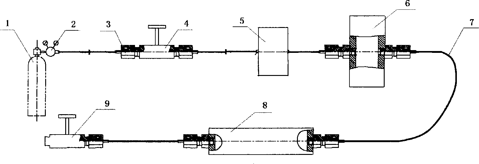
[0035] One method of leak-tight air sealing is:

[0036] The first step is to connect the pipeline: connect the deflation valve 9 at one end of the equipment gate sealing chamber 8, connect one end of the buffer tank 6 through the pipeline 7 at the other end of the equipment gate sealing chamber 8, and connect the other end of the buffer tank 6 with the One end of the air leak tester 5 is connected, the other end of the air leak tester 5 is connected with one end of the spherical connecting rod 3 through the stop valve 4, and the other end of the spherical connecting rod 3 is connected with the gas cylinder 1 through the pressure reducing valve,

[0037] Such as figure 1 shown;

[0038] The second step is to conduct a soap bubble test on the pipeline to check the tightness of the pipeline;

[0039] The third step, leakage calculation

[0040] The leakage from the double sealing gasket is calculated by the following calculation formula: P 2

[0041] R ...


PUM


Abstract

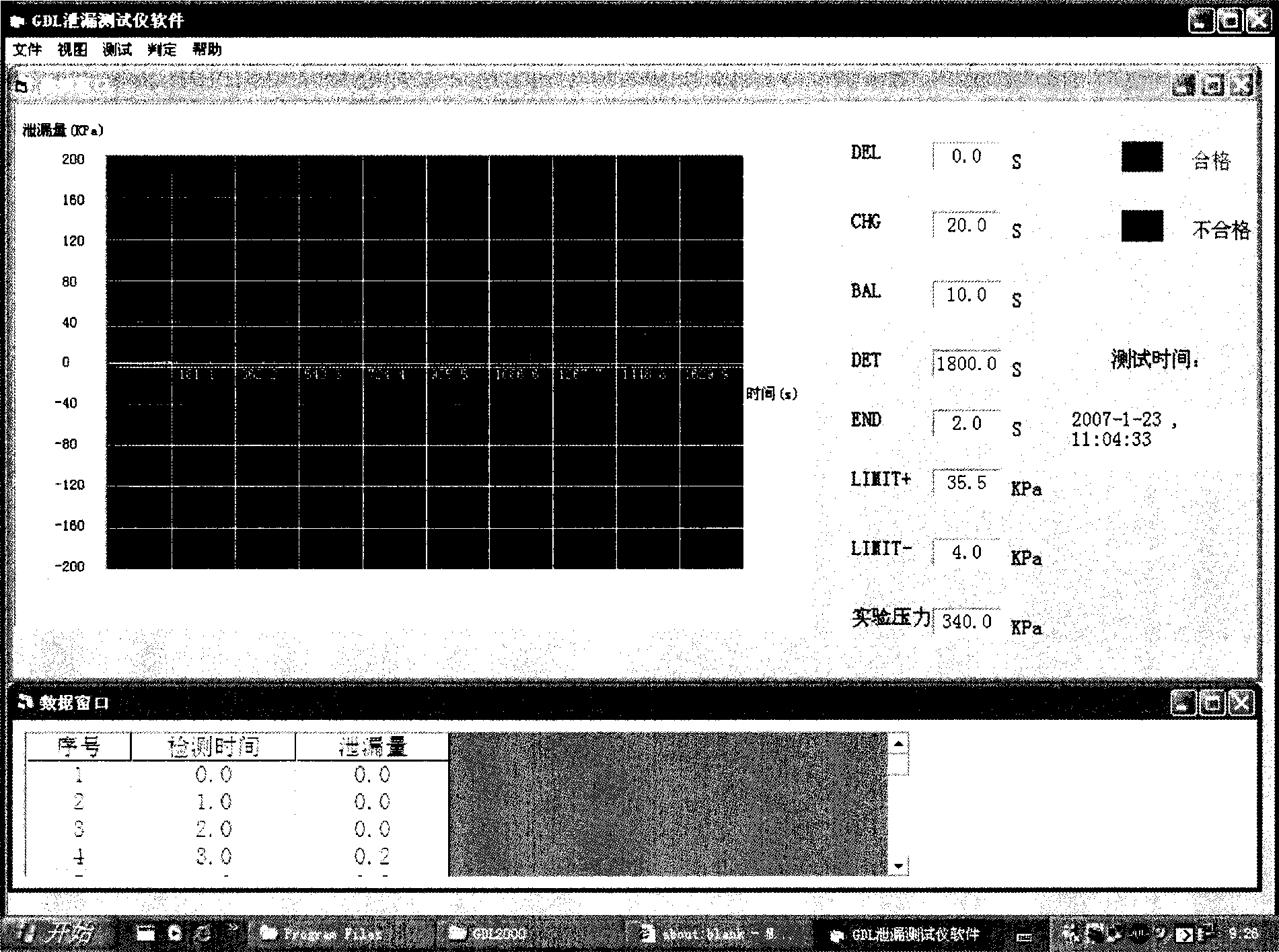
The invention relates to a method for sealing the leakage of small amount of air. The method is characterized in that: a pipeline is connected, one end of an equipment gate sealing cavity is connected with a release valve, the other end of the equipment gate sealing cavity is connected with one end of a buffer tank through the pipeline, the other end of the buffer tank is connected with one end of an air leakage tester, the other end of the air leakage tester is connected with one end of a spherical connecting rod through a disconnecting valve, and the other end of the spherical connecting rod is connected with an air bottle through a reducing valve; the soap bubble experiment on the pipeline is performed to detect the leak tightness of the pipeline; the leakage amount is calculated, according to the requirement of the experiment, a computer is connected with the tester and the experimental data is inputted by the computer; the air bottle is opened, the equipment gate sealing cavity is pressurized and added with nitrogen. The method has the advantages that the air sealing leakage amount can be measured accurately to the utmost degree, and the computer can help people understand the air leakage amount curve, the instantaneous leakage amount and the data record in real time during the whole experiment process.

Description

technical field [0001] The invention relates to a method for sealing leakage of trace air, which is mainly used in the nuclear power plant industry and belongs to the technical field of leakage testing. Background technique [0002] The equipment gate on the containment of the nuclear power plant is closed when the reactor is running, and it is part of the overall seal of the containment; it can withstand the loads of various design basis accidents (temperature, pressure, and forced displacement of concrete, etc.) to maintain safety Shell integrity and tightness. According to the design specifications, the sealing of the equipment gate can allow a small amount of air leakage, so a sealing leak test is required to verify the reliability of the equipment during the manufacturing process of the equipment gate. The commonly used test methods are: [0003] 1. Use two pressure gauges to judge whether it is qualified according to the reading value of the pointer of the pressure g...

Claims


Application Information

Patent Timeline
IPC IPC(8): G01M3/02G01M3/14G01M3/32
Inventor 吴立文高理远袁强曹福勤
Owner SHANGHAI ELECTRIC POWER GENERATION EQUIPMENT CO LTD
Learn More