
High temperature heat integration system for oil-extraction plant and use thereof

A combined system and refinery technology, applied in heat storage heaters, fluid heaters, heat exchanger types, etc., can solve the problems of increasing the fuel consumption of heating furnaces, optimizing matching, and loss of steam, reducing refining costs, The effect of optimizing the heat exchange network and saving medium pressure steam

Active Publication Date: 2011-01-26
SHANGHAI YOUHUA PROCESS INTEGRATED TECH CO LTD
View PDF0 Cites 0 Cited by
  • Summary
  • Abstract
  • Description
  • Claims
  • Application Information

AI Technical Summary

Problems solved by technology

[0006] The energy utilization of the above-mentioned unit devices has not been systematically considered, and has not been optimized and matched from the whole plant. The heat of the high-temperature stream is used to generate steam; the generated steam enters the steam pipe network and is transported to other devices as fuel for other devices. Heat source; this method has many energy conversion links, and the steam transmission also has losses. The final result is that the heat utilization efficiency of the high-temperature stream is low, high-quality and low-use, and serious waste. It also increases the high-quality fuel of the heating furnace. consume

Method used

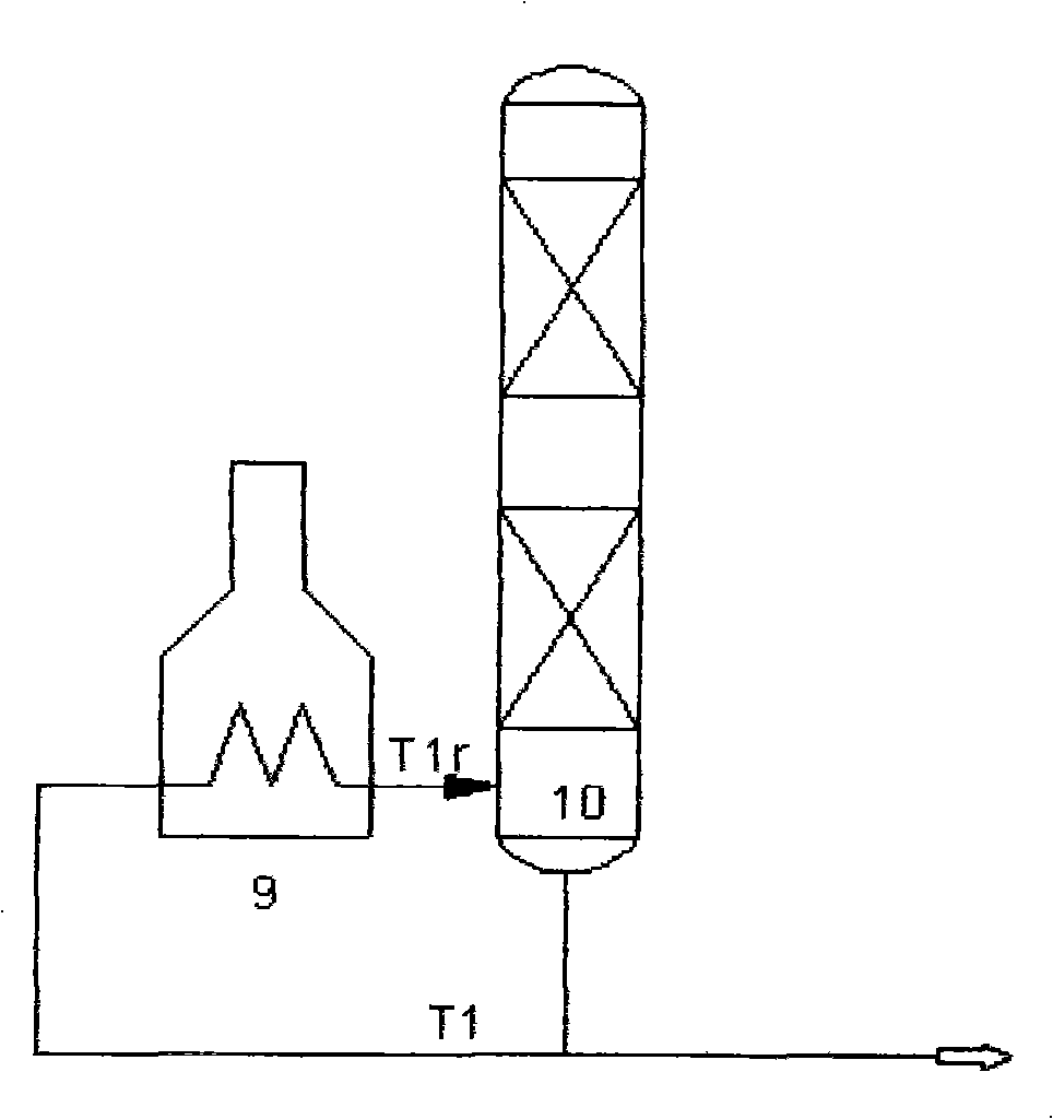
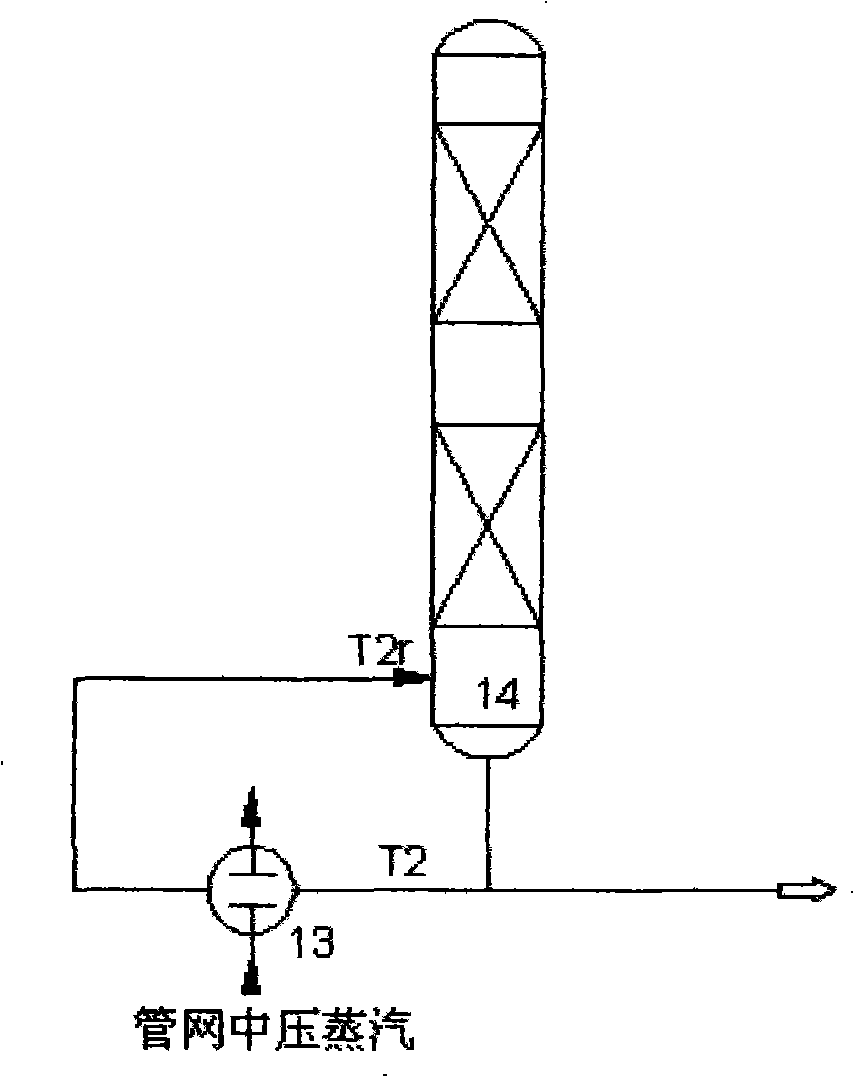

Image

  • High temperature heat integration system for oil-extraction plant and use thereof
  • High temperature heat integration system for oil-extraction plant and use thereof
  • High temperature heat integration system for oil-extraction plant and use thereof

Examples


Embodiment Construction

[0022] The present invention will be further described below.

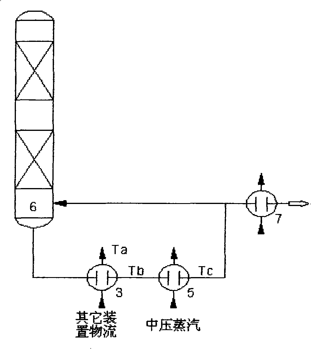
[0023]The heat conduction oil at 200-250°C enters the shell side of the fifth heat exchange device 16 newly added in the heat source device 11 through the heat medium pipe, and the heat source that comes out of the bottom outlet of the fractionation tower 6 in the tube side of the fifth heat exchange device 16 The material flow of device 11 is heat exchanged. After the heat exchange, the temperature of the material flow of heat source device 11 is Td=290-260°C. The streams are heat-exchanged, the streams entering the shell side of the first heat exchange equipment 3 are heat-exchanged to Ta=170-230°C, the streams of the heat source device 11 are heat-exchanged to Tb'=280-260°C, and then the streams of the heat source device 11 Then enter the tube side of the second heat exchange equipment 5 and exchange heat with the stream entering the shell side of the second heat exchange equipment 5 until Tc = 270-250 ° C. Aft...


PUM


Abstract

The invention relates to a heat exchange system for high temperature heat of a plant, in particular to an oil refining plant high-temperature heat integration system designed for using high-temperature mass flow heat. The system is characterized in that three independent heat source devices are connected through thermal medium pipes and heat-conducting oil in the thermal medium pipes are used as a heat-transfer medium to form heat integration, so as to collect and use high-temperature heat. Compared with the prior art, the system optimizes a heat exchange network, saves fuel gases and steam in a reboiler at the tower bottom, reduces energy consumption of equipment, lowers oil refining cost and improves economic benefits.

Description

[technical field] [0001] The invention relates to a heat exchange system for high-temperature heat in a factory, in particular to a high-temperature heat combined system of an oil refinery designed by utilizing the heat of a high-temperature stream. [technical background] [0002] At present, the utilization of high-temperature heat in known factories is characterized by utilization in each device, such as steam generation, etc., and the comprehensive utilization of heat is not considered between each unit device. On the other hand, the hot-trap streams of other unit devices need to be heated to raise the temperature, and some streams need to consume fuel through heating furnaces or use medium-pressure steam to heat up the temperature of the hot-trap streams, which has not been realized in the whole plant The multi-stage utilization of high-temperature potential heat causes energy waste, which is inconsistent with the scientific energy utilization principle of "corresponding...

Claims


Application Information

Patent Timeline
Patent Type & Authority Patents(China)
IPC IPC(8): F24H7/02F28D7/10
Inventor 张高博张旭东
Owner SHANGHAI YOUHUA PROCESS INTEGRATED TECH CO LTD
Learn More