
Precision glass cutting-table tool bit assembly

A glass and table-cutting technology, applied in glass cutting devices, glass manufacturing equipment, manufacturing tools, etc., can solve problems such as easy existence of included angles, difficulty in keeping two vertical planes parallel, and edge bursting at the glass incision.

Inactive Publication Date: 2011-05-25
ANHUI JINGLING GLASS MACHINERY
View PDF0 Cites 0 Cited by
  • Summary
  • Abstract
  • Description
  • Claims
  • Application Information

AI Technical Summary

Problems solved by technology

Restricted and affected by factors such as the manufacturing accuracy and assembly accuracy of the existing cutter head assembly, the matching accuracy between the knife box and the knife box track, the vertical plane where the knife wheel is located and the normal line of the precision glass cutting table knife box track are located. There are easy angles between the vertical planes, in other words, it is difficult for the two vertical planes to remain parallel
[0007] When in use (that is, when the knife box of the existing knife head assembly is used to cut glass), because the knife wheel cannot rotate, adjust and find its position, the glass cut is not a parallel straight edge, and the glass cut is not straight. The phenomenon of edge bursting occurs, and the scrap rate increases. Therefore, the cutting accuracy of the knife box with the existing knife head assembly is poor, and it cannot meet the needs of high-precision glass cutting.

Method used


Image

  • Precision glass cutting-table tool bit assembly
  • Precision glass cutting-table tool bit assembly
  • Precision glass cutting-table tool bit assembly

Examples


Embodiment Construction

[0019] The present invention will be further described below by embodiment and accompanying drawing thereof:

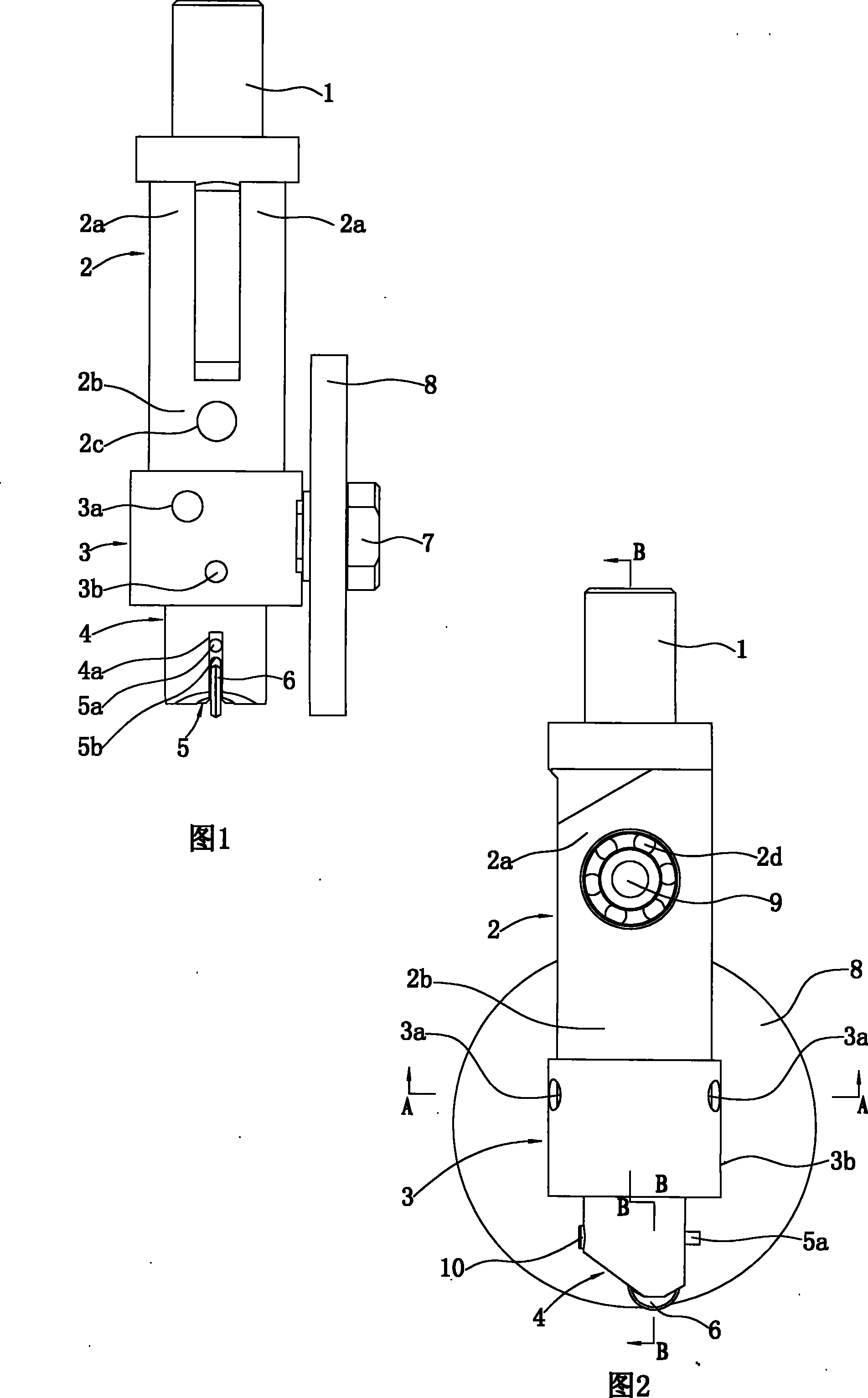
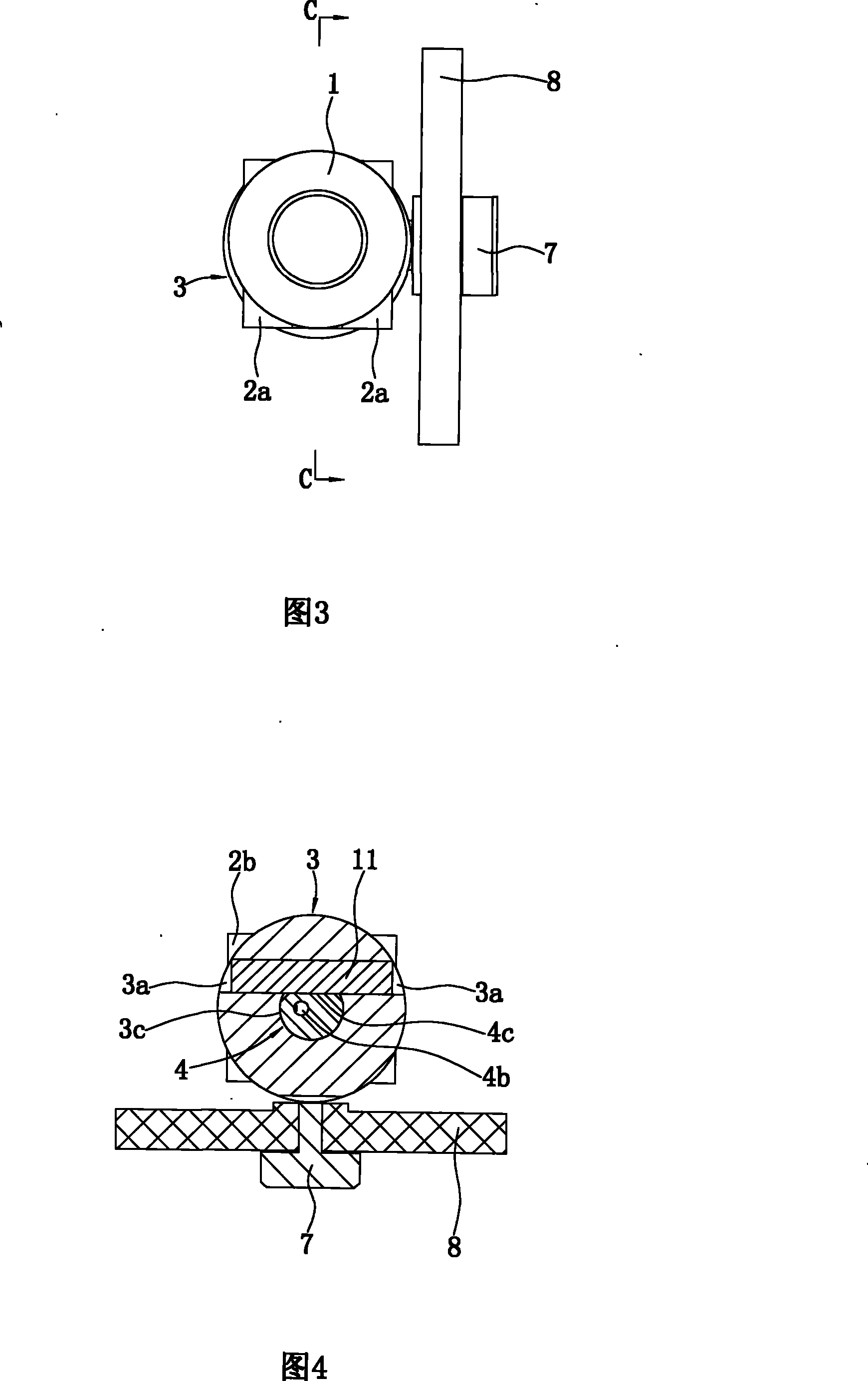
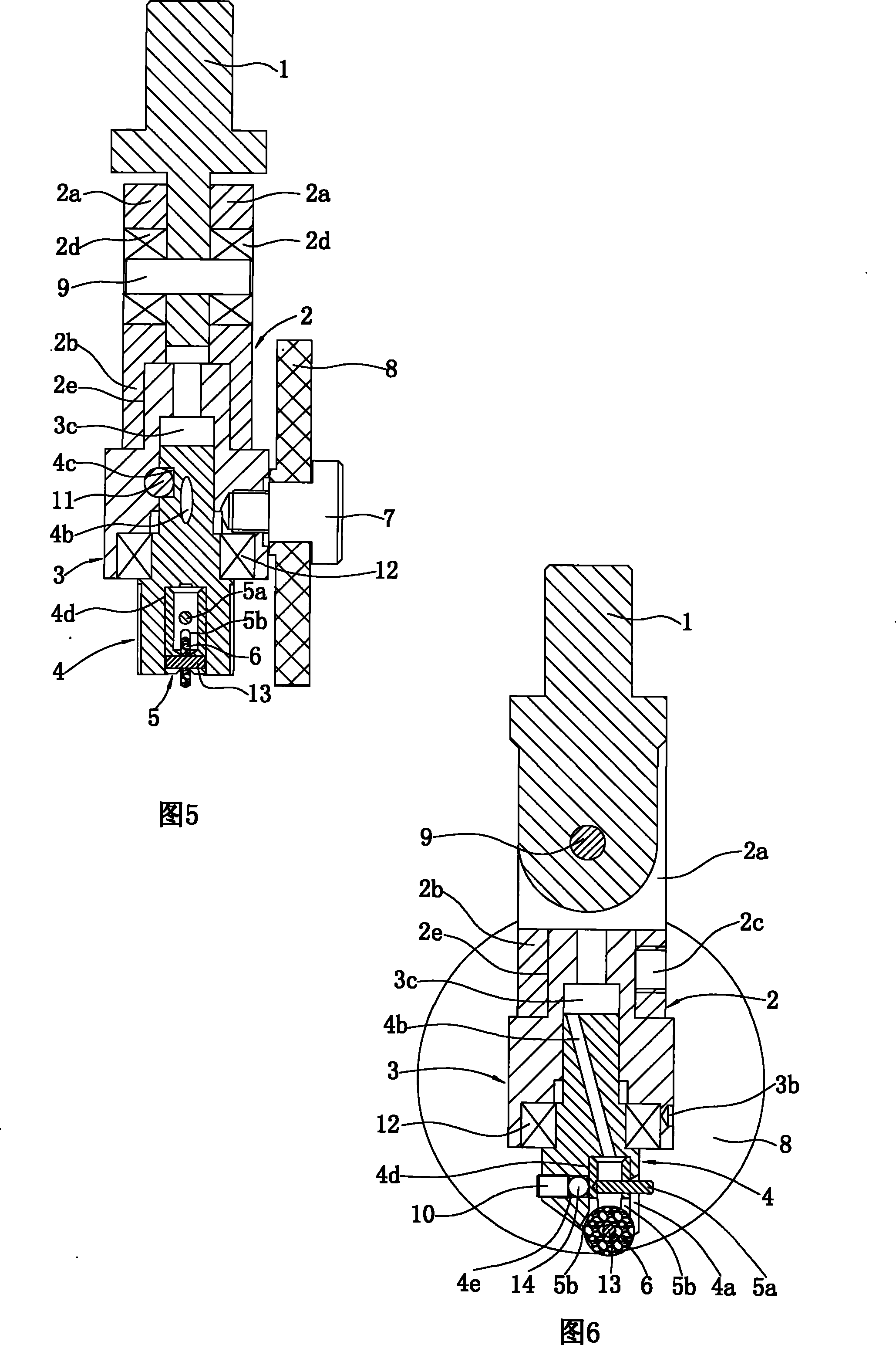
[0020] Referring to Fig. 1-Fig. 6, this precision glass cutting table cutter head assembly includes vertically arranged joint 1, pendulum block 2, fixed column 3, rotating column 4, nylon wheel 8, knife holder 5, knife wheel 6 and left and right horizontal The pin shaft 9, the screw 7, and the cutter wheel shaft 13 are arranged and the axes are parallel to each other.

[0021] The upper part of the pendulum block 2 is two left and right spaced and symmetrical ear plates 2a, and the lower part is a square block 2b. A vertically arranged bearing 2d is installed in each ear plate 2a. The center of the square block 2b has a vertical through-hole 2e. , The front side has a threaded hole 2c communicating with the light hole 2e.

[0022] There is a stepped hole 3c which runs up and down and has a circular cross-section in the fixed column 3. A bearing 12 is horizontally ins...


PUM


Abstract

The invention provides a precision glass cutting table cutter head assembly, wherein the lower part of a swinging block is fixedly connected with a fixing column, the inside of the fixing column is provided with a step hole, and the inside of an opening on the lower end of the step hole is provided with a bearing; the middle part of the fixing column is penetrated along the height direction, and is eccentrically provided with two horizontal pin holes which are symmetrical to each other, the shaft line of each pin hole is vertical to the axial line of the fixing column and the axial line of a pin shaft, an interval is arranged between the axial lines of the pin hole and the fixing column, the outer end of each pin hole is positioned on the outer column surface of the fixing column, and theinner end of each pin hole is communicated with the step hole; the upper part of a rotary column is communicated with a horizontal penetration square groove, the upper part of the rotary column is inrotary fit with the step hole, the middle part of the rotary column is connected with the fixing column through the bearing, and the lower part of the rotary column is provided with a cutter holder with a cutting wheel; a control pin orderly runs through one pin hole, a square groove and the other pin hole and then is arranged between the fixing column and the rotary column; and the middle part of the fixing column in the height direction is in screw-thread fit with a bolt passing through the center of a nylon wheel. When the assembly is used, the maximum clockwise or counterclockwise rotary angle of the cutting wheel is 15 degrees. A cutter box adopting the assembly has high slitting precision.

Description

technical field [0001] The invention relates to parts in a precision glass table cutting knife box as a glass cutting tool, in particular to a precision glass table cutting knife head assembly connected with a pole or a connecting plate in the knife box. Background technique [0002] At present, there are two kinds of precision glass cutting table knife boxes as glass cutting tools. [0003] One structure is: there are several through holes on the body or a rail groove on one side, the upper part of the vertical rod is fastened with the adjusting cross arm, the middle part is connected with the body through a linear bearing, the lower end is fixed with the cutter head assembly, and the positioning bolt Cooperate with the adjusting cross-arm thread, the upper end of the guide pin is fastened to the adjusting cross-arm, the spring is connected between the lower end and the upper end of the screw with groove, the lower end of the guide pin, the spring and the upper part of the ...

Claims


Application Information

Patent Timeline
Patent Type & Authority Patents(China)
IPC IPC(8): C03B33/02
Inventor 徐金陵
Owner ANHUI JINGLING GLASS MACHINERY
Learn More