
Planar magnetron sputtering cathode capable of improving target material utilization rate

A technology of magnetron sputtering and utilization rate, which is applied in the direction of sputtering coating, metal material coating process, ion implantation plating, etc., can solve the problem of high cost of target material, and achieve the effect of improving target material utilization rate

Inactive Publication Date: 2009-04-29
湖南玉丰真空科学技术有限公司
View PDF0 Cites 19 Cited by
  • Summary
  • Abstract
  • Description
  • Claims
  • Application Information

AI Technical Summary

Problems solved by technology

Generally speaking, the target utilization rate of planar cathodes is usually only 20%-28%. In the coating cost, the cost of the target is relatively high.

Method used


Image

  • Planar magnetron sputtering cathode capable of improving target material utilization rate
  • Planar magnetron sputtering cathode capable of improving target material utilization rate
  • Planar magnetron sputtering cathode capable of improving target material utilization rate

Examples


Embodiment 1

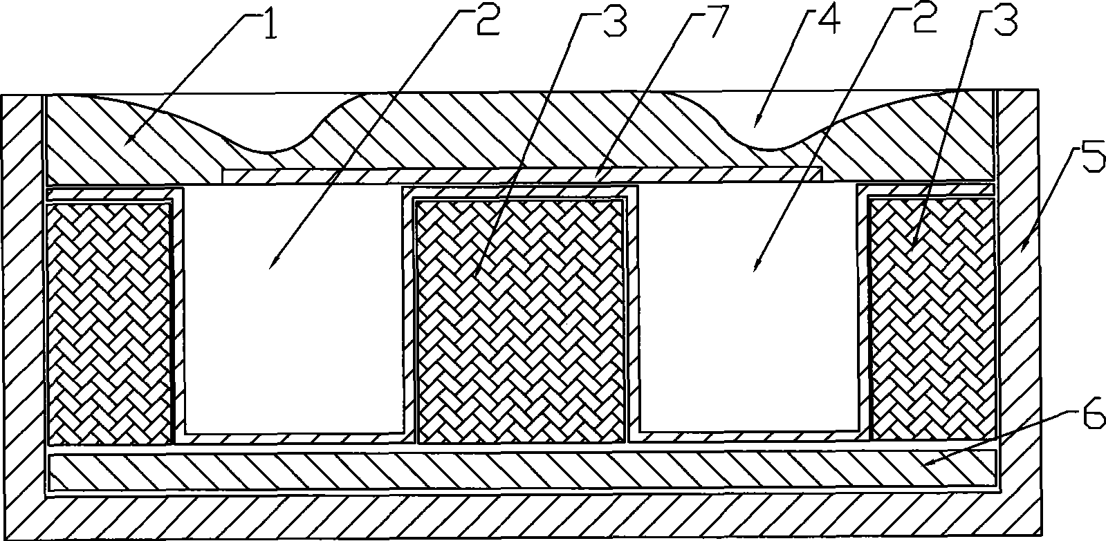
[0015] Embodiment 1, the present invention is composed of a cathode casing 5, a magnetic shoe 6, a magnet 3, a cooling channel 2 and a target 1, etc., and a thin metal sheet 7 for adjusting the magnetic field is arranged between the target 1 and the cooling channel 2 , the metal sheet 7 is made of magnetically conductive metal. The metal sheet 7 can be fixedly connected to the bottom of the target 1 . And a groove can be set at the bottom of the target material 1 , and the metal sheet 7 is embedded in the groove set at the bottom of the target material 1 .

[0016] In the present invention, on the basis of the existing cathode, in order to improve the utilization rate of the target, a metal sheet 7 for adjusting the magnetic field is inserted at the interface between the target material and the cooling channel. And the high-temperature-resistant metal material makes the horizontal magnetic field on the surface of the target uniform in a wider range, and the magnetic field int...

Embodiment 2

[0018] Embodiment 2, the thin metal sheet 7 of the present invention can also be arranged on the bottom of the target 1 in a movable fit, so as to facilitate the adjustment of the magnetic field intensity distribution curve. refer to Figure 1 to Figure 4 , all the other are with embodiment 1.

Embodiment 3

[0019] Embodiment 3, in order to improve the cooling effect, in the present invention, a transition layer with good thermal conductivity can also be provided between the metal foil 7 and the target material 1 . refer to Figure 1 to Figure 4 , and the rest are the same as the above-mentioned embodiment.

[0020] Obviously, the metal flake 7 in the present invention can be a whole piece of metal, or two or more than two pieces of metal flakes.


PUM


Abstract

The invention relates to a planar magnetron sputtering cathode which can increase the utilization rate of a target and belongs to a planar magnetron sputtering cathode. The planar magnetron sputtering cathode mainly solves the problems that the utilization rate of the target of the prior planar cathode is comparatively low and the like. The key points of the technical proposal are as follows: the planar magnetron sputtering cathode consists of a cathode body shell (5), a magnetic boot (6), a magnet (3), a cooling channel (2) and the target (1), wherein a leaf metal (7) for adjusting a magnetic field is arranged between the target (1) and the cooling channel (2); and the leaf metal (7) is made of magnetic metal material. The leaf metal (7) is fixedly connected with the bottom of the target (1). The bottom part of the target (1) is provided with a groove, and the leaf metal (7) is embedded in the groove arranged on the bottom part of the target (1). The planar magnetron sputtering cathode can enable the horizontal magnetic field on the surface of the target to achieve uniformity in a wider range, thereby improving the utilization rate of the target to 35 to 38 percent from normally 20 to 28 percent. The planar magnetron sputtering cathode can be widely applied to the technical field of magnetron sputtering coating.

Description

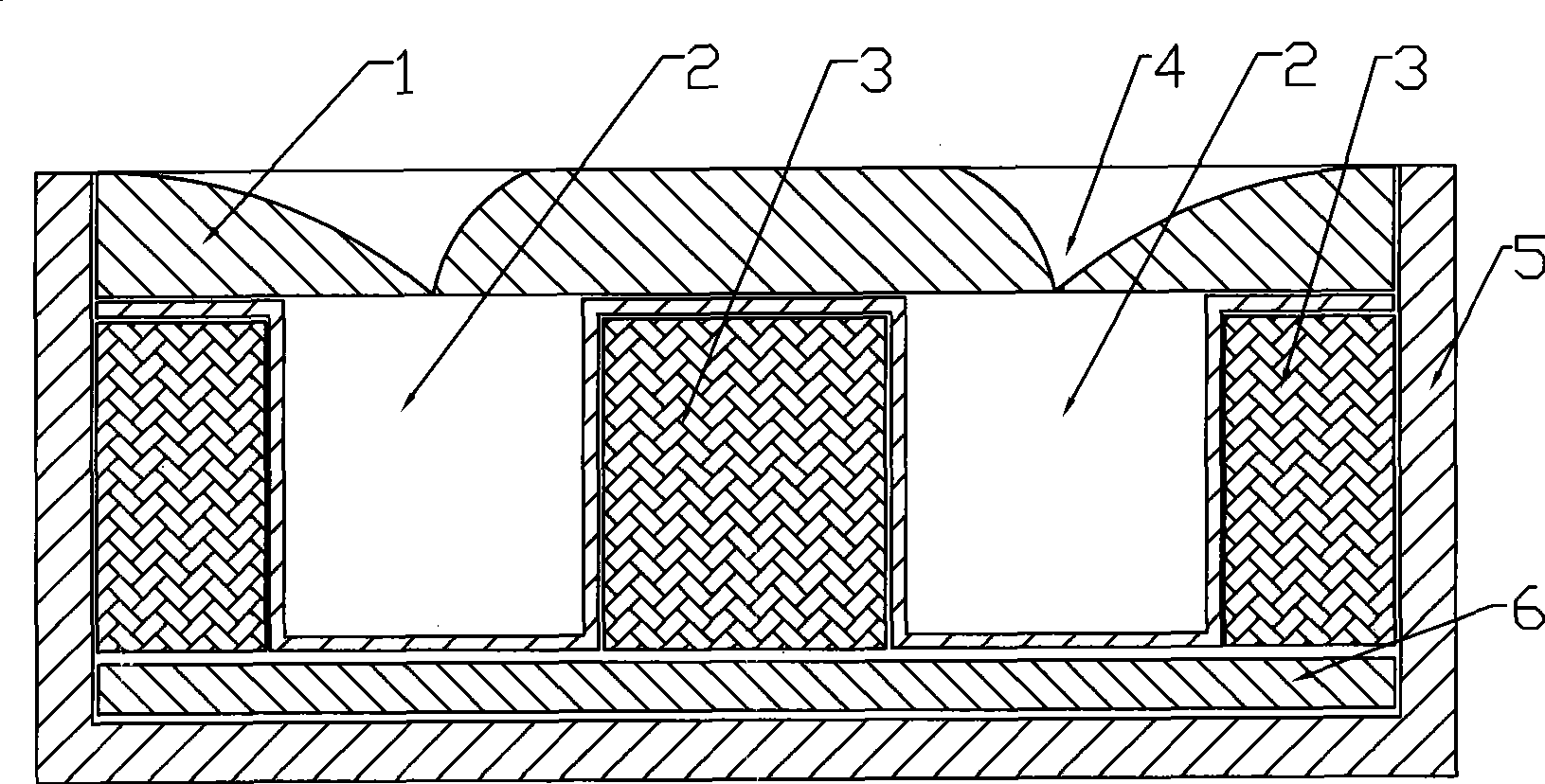
technical field [0001] The invention relates to a planar magnetron sputtering cathode used in vacuum magnetron sputtering coating equipment. Background technique [0002] At present, in the application field of magnetron sputtering coating technology, the widely used planar magnetron sputtering cathode is generally composed of a cathode body shell 5, a magnetic shoe 6, a magnet 3, a cooling channel 2, a target 1, etc., see figure 1 . During the working process, the magnetic field intensity distribution parallel to the target surface can be referred to figure 2 , during the sputtering process, the stronger the magnetic field strength, the higher the sputtering rate, and the greater the consumption of the target. After a period of sputtering, the surface of the target 1 will appear as figure 1 The sputter trench 4 is shown. The deepest sputter groove corresponds to the strongest magnetic field. When the sputtering groove is deep to a certain extent, the target 1 needs to ...

Claims


Application Information

Patent Timeline
IPC IPC(8): C23C14/35
Inventor 陈理李国强
Owner 湖南玉丰真空科学技术有限公司
Learn More