
High-capacity planar magnetron sputtering cathode

A magnetron sputtering, high-power technology, applied in the direction of sputtering plating, ion implantation plating, metal material coating process, etc., to achieve high power and avoid the effect of cooling medium corrosion

Active Publication Date: 2010-09-22
HUNAN YUFENG VACUUM SCI & TECH CO LTD
View PDF0 Cites 4 Cited by
  • Summary
  • Abstract
  • Description
  • Claims
  • Application Information

AI Technical Summary

Problems solved by technology

Existing planar magnetron sputtering cathodes have magnets soaked in water, which will demagnetize after a long time

Method used


Image

  • High-capacity planar magnetron sputtering cathode
  • High-capacity planar magnetron sputtering cathode
  • High-capacity planar magnetron sputtering cathode

Examples


Embodiment 1

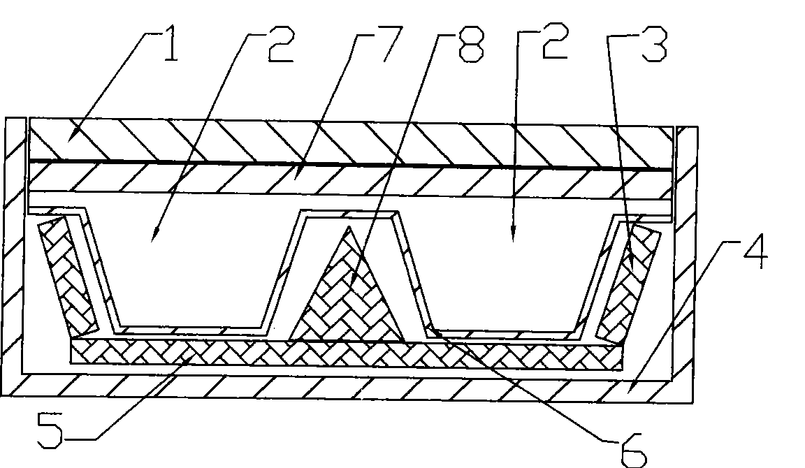
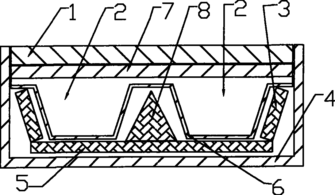
[0012] Embodiment 1, the main part of the present invention is divided into a cathode main part and a target part. It is composed of cathode body 4, magnetic shoe 5, magnet 3, cooling channel 2, etc. The cooling channel shell 6 can be made of metal material, and the target 1 is installed on the upper part of the cathode body 4, in the inner cavity of the cathode body A closed cooling passage 2 is provided, and a magnetic shoe 5 is provided between the bottom of the inner cavity of the cathode body 4 and the cooling passage 2, and a magnet 3 is provided between the cooling passage 2 and the magnetic shoe 5, so that inside the cathode body 4 An independent cooling channel is formed, and the magnet 3 can be a permanent magnet. This structure enables the present invention to provide a large flow of cooling water, or other cooling liquids or gases during the working process, thereby ensuring that the cathode is cooled. The magnetic shoe 5 and the magnet 3 are installed on the lowe...

Embodiment 2

[0013] Embodiment 2, the cooling channel 2 of the present invention can be composed of the cooling channel housing 6 and the heat conduction plate 7, so that the cathode body part is composed of the cathode body 4 and the magnetic shoe 5, the magnet 3, the cooling channel 2, the cooling channel housing 6, the heat conduction The cooling channel shell 6 can be designed as a groove-like structure with an open upper part, and a heat conduction plate 7 is arranged on the upper part of the cooling channel shell 6, and the upper part of the cooling channel shell 6 and the heat conduction plate 7 form a sealed fit, so that The cooling channel shell 6 and the heat conduction plate 7 form the cooling channel 2 together. The heat conduction plate 7 is made of a material with better thermal conductivity, and its thickness is made as small as possible, thereby improving heat conduction, heat dissipation and cooling efficiency. It is the thinner heat conduction plate 7 that is in contact wi...

Embodiment 3

[0014] Embodiment 3, the cross-section of the cooling channel housing 6 of the present invention can be a trapezoidal cooling groove with a wide top and a narrow bottom, and a strip magnet 3 that is matched with the cooling channel housing 6 is provided on the outside of the cooling channel 2 . By designing the cooling channel 2, the shape and installation position of the magnet can be changed; the magnet 3 at different positions can be designed into different shapes and installed according to different angles or positions according to the requirements of working parameters. refer to figure 1 and figure 2 , and the rest are the same as the above-mentioned embodiment.


PUM


Abstract

The invention relates to a high-power planar magnetron sputtering cathode, which belongs to a double silver-layer low emissivity film and mainly solves the technical problems that the magnet of the prior planar magnetron sputtering cathode is steeped in water and will be degaussed after being used for a long time and the like. The key points of the technical proposal are as follows: the high-power planar magnetron sputtering cathode consists of a cathode body (4), a target (1) and a magnet, wherein the target (1) is arranged on the upper part of the cathode body (4); an airtight cooling channel (2) is arranged in the inner cavity of the cathode (4); a magnetic boot (5) is arranged between the bottom and the cooling channel (2) in the inner cavity of the cathode body (4); and the magnet (3) is arranged between the cooling channel (2) and the magnetic boot (5). Because an independent cooling channel is arranged in the cathode body, the magnet does not contact with cooling media to avoidthe permanent magnet from being eroded by the cooling media; besides, high-power planar magnetron sputtering cathode is designed with a heat conduction plate made of materials with high thermal conductivity to contact with the target in a large area, so that the target can be cooled sufficiently and the cathode can bear higher power. The high-power planar magnetron sputtering cathode can be widely applied to a vacuum magnetron sputtering coating device.

Description

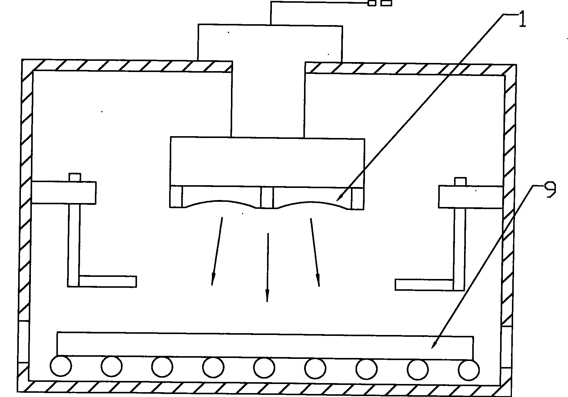
technical field [0001] The invention relates to a high-power planar magnetron sputtering cathode used in vacuum magnetron sputtering coating equipment. Background technique [0002] At present, the vacuum magnetron sputtering method is to place the substrate to be plated in a vacuum chamber, and pass through the working gas (argon, oxygen, nitrogen, etc.), when the sputtering cathode and anode are energized, the cathode is negative Potential, due to the action of the high-voltage electric field, the gas (argon) molecules are ionized to form plasma, and the positively charged argon particles will hit the surface of the cathode target at high speed under the acceleration of the electric field, and the metal ions on the target surface will be knocked out , the trajectory of the ions in the orthogonal electromagnetic field is a cycloid, and they are gradually deposited on the glass surface to form a thin film. Working principle of planar magnetron sputtering cathode figure 2...

Claims


Application Information

Patent Timeline
Patent Type & Authority Patents(China)
IPC IPC(8): C23C14/35
Inventor 陈理李国强
Owner HUNAN YUFENG VACUUM SCI & TECH CO LTD
Learn More