Cavity filter structure mathematical response model and cavity filter for mobile communication network thereof

A cavity filter and response model technology, applied in waveguide-type devices, resonators, electrical components, etc., can solve the problems of increased insertion loss in the center of the passband, unequal coupling capacitance of the resonance circuit, complex structure, etc. The process is simplified, suitable for mass production, and the effect of no-load Q value is large

Inactive Publication Date: 2009-04-15
丹东华讯电子有限公司
View PDF0 Cites 8 Cited by
  • Summary
  • Abstract
  • Description
  • Claims
  • Application Information

AI Technical Summary

Problems solved by technology

Most of these cavity filters are designed and manufactured with Chebyshev as the mathematical response model. Since the unloaded Q value of the actual cavity filter is limited, the application of the Chebyshev mathematical response model must be carried out by pre-distortion design. In this way, the insertion loss in the center of the passband increases, so it is difficult to meet the requirements of signal transmission and interference suppression required for the uplink and downlink of the base station in the TD-SCDMA network
In particular, some technical problems in the cavity filter manufactured by the Chebyshev mathematical response model are fatal: the coupling capacitance of the resonant circuit is not equal, the inductance of the resonant circuit is not equal, and the coupling amount of each circuit is not uniform. The size and adjustment are not uniform, and the structure is complex, which greatly increases the complexity and difficulty of processing and debugging

Method used


Image

  • Cavity filter structure mathematical response model and cavity filter for mobile communication network thereof
  • Cavity filter structure mathematical response model and cavity filter for mobile communication network thereof
  • Cavity filter structure mathematical response model and cavity filter for mobile communication network thereof

Examples


Embodiment Construction

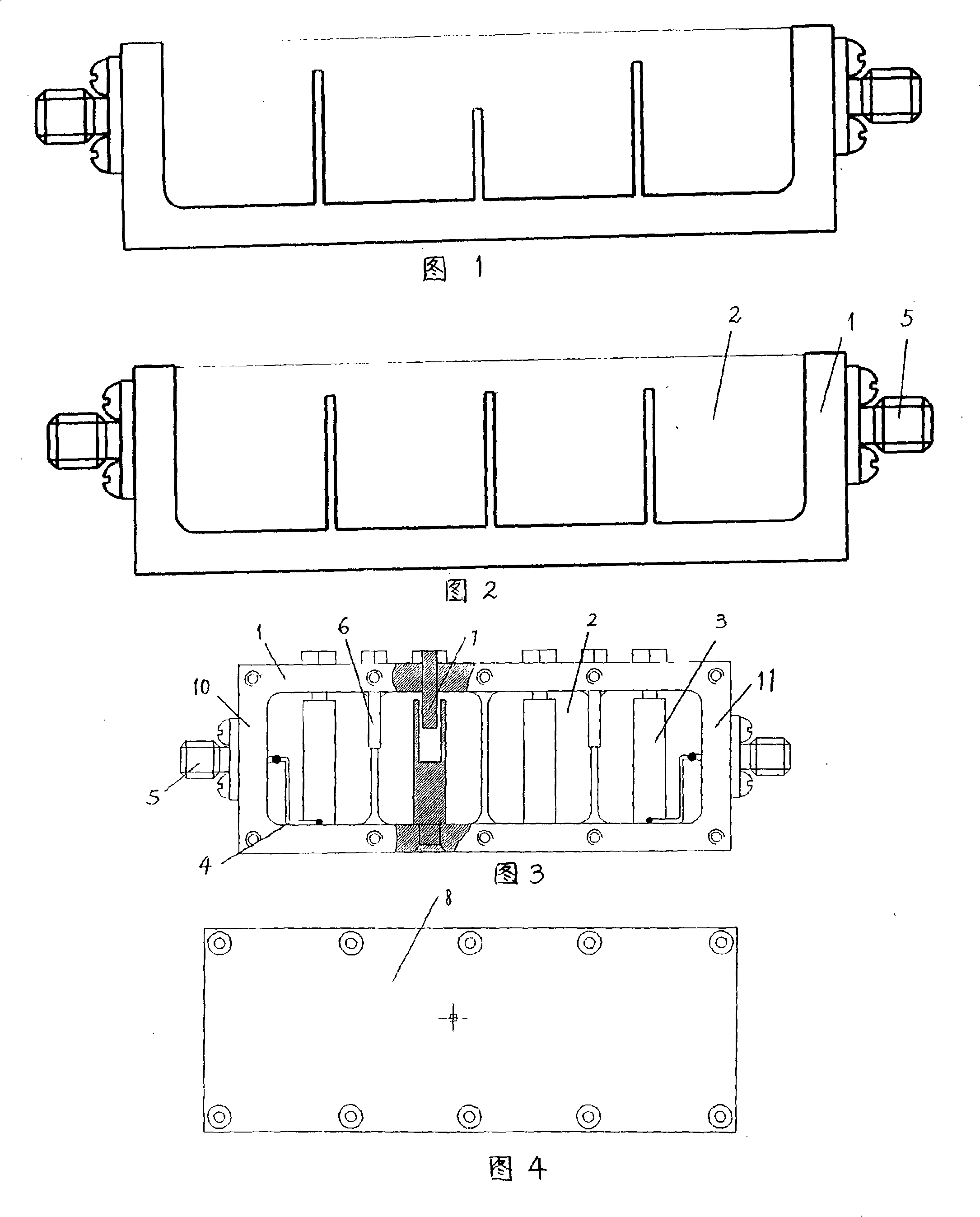
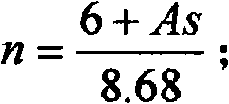
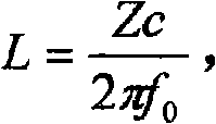
[0017] The mathematical response model of the cavity filter structure disclosed in the application of the present invention, before implementing the design and derivation according to the mathematical response model, first determine the following main electrical parameters of the cavity filter: the center frequency f 0 , bandwidth, insertion loss, out-of-band rejection A s , input and output impedance R 0 , and then determine the structural size of the cavity filter by the following steps:

[0018] ①. Determine the number of cavity filter sections n = 6 + As 8.68 ;

[0019] ②. The resonant cavity of the cavity filter is a square cavity, and the ratio of the side length b of the square cavity to the outer diameter d of the resonant rod, that is, the unloaded Q value of the cavity is the best when b / d is between 3-4. Determine a value between 4, and get the...


PUM


Abstract

The invention relates to a cavity filter used for a microwave communicating system. Aiming at solving the technical problems of disunited structure size and complex structure of the existing cavity filter manufactured by a Chebyshev mathematics response model, the invention provides a mathematics response model of a cavity filter structure and a cavity filter used for a movable communicating network; the mathematics response model thereof adopts an isoparametric element lowpass prototype as the designed mathematics response model of the cavity filter structure and leads the cavity filter structure obtained according to the mathematics response model to respectively have united and consistent structure sizes on the resonance cavity, resonance rod, coupling adjusting rod and resonance cavity clapboard thereof, thus leading the product manufacturing and processing technique of the cavity filter to be greatly simplified; simultaneously the assembled cavity filter is easier to be debugged and is suitable for batch production. Another advantage of the technical scheme is as follows: under the condition of meeting stopband attenuation, the central loss of a benchmark passband is reduced to the minimum; moreover, the unloaded Q value of the cavity can be guaranteed to be maximal and the insertion loss of the cavity filter is minimal.

Description

technical field [0001] The invention relates to a band-pass filter, a component of a microwave communication system, and in particular to a cavity filter for a mobile communication network. Background technique [0002] In the mobile communication network, especially in the current 3G mobile communication network, the filter plays a very important role, and it is required to have the characteristics of low insertion loss and high selectivity. Taking the construction of TD-SCDMA base station as an example, since TD-SCDMA uses a smart antenna with a relatively complex structure, the nonlinearity will exceed that of other ordinary base station antennas, so the low noise increase of TD-SCDMA affected by electromagnetic effects will be higher than that of ordinary base stations. Therefore, a large number of band-pass filters with low insertion loss and high selectivity are required in the uplink and downlink of the base station. In order to meet the high requirements of the mobi...

Claims


Application Information

Patent Timeline
IPC IPC(8): H01P1/208H01P7/06
Inventor 潘振增
Owner 丹东华讯电子有限公司
Why Eureka
Try Eureka