Auxiliary correcting device of exposure image partial difference
A technology for correcting device and deviation, applied in the field of photoengraving technology, can solve problems such as complicated operation, and achieve the effect of ensuring image quality
Inactive Publication Date: 2010-11-10
HANS LASER TECH IND GRP CO LTD +1
View PDF0 Cites 0 Cited by
- Summary
- Abstract
- Description
- Claims
- Application Information
AI Technical Summary
Problems solved by technology
This method is more complicated to operate, and the calibration result has a greater relationship with the experience of the operator, so it is not suitable for occasions that require higher precision.
Method used
View moreImage
Smart ImageViewing Examples
Examples
Embodiment Construction
Login to View More PUM
 Abstract
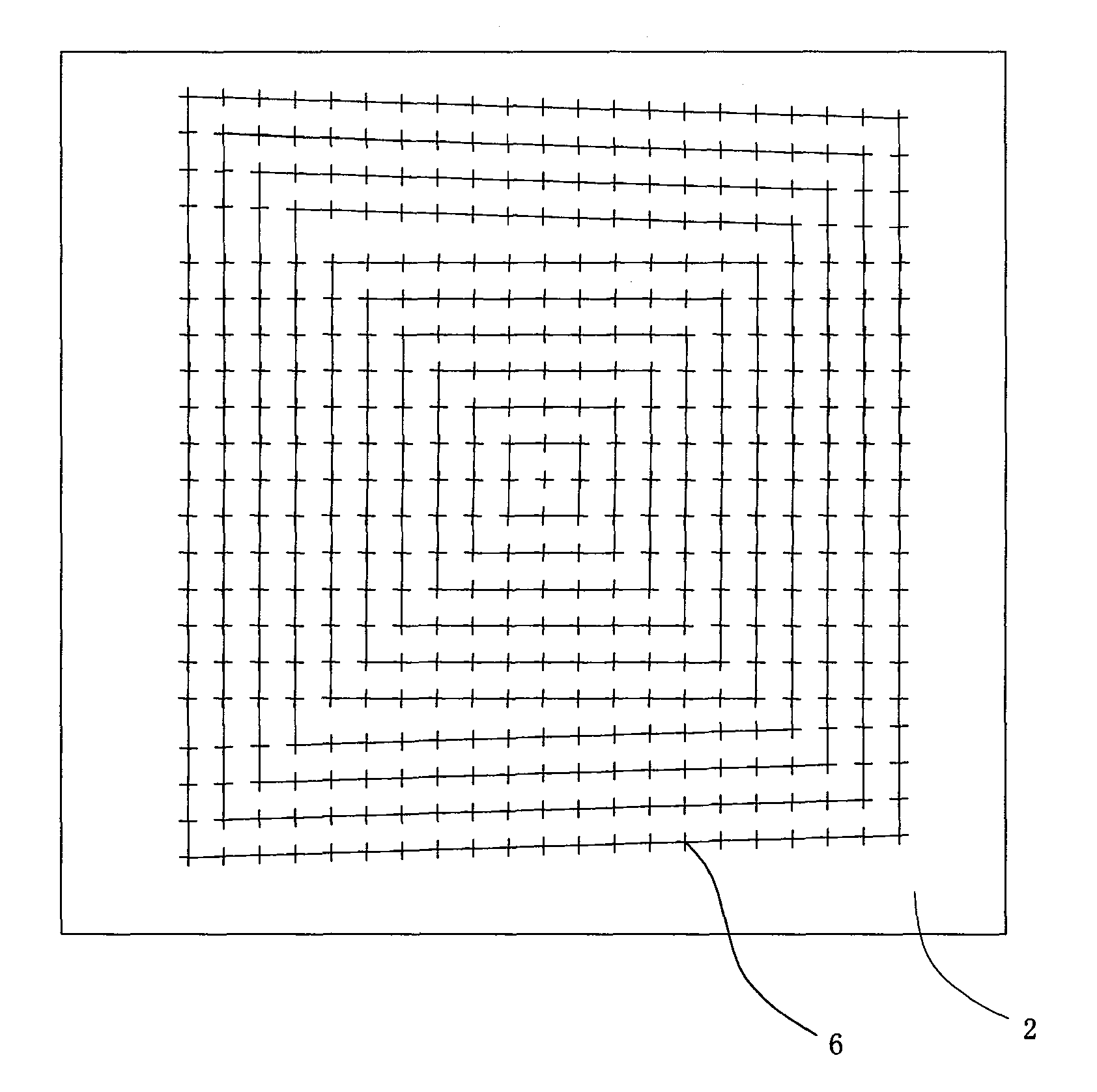
The invention relates to an auxiliary alignment apparatus for the deviation of an exposure image, comprising a movement platform, an image system and a processing system which is connected with the movement platform and the image system. The image system moves by controlling the movement platform, so as to acquire image data of a test printing plate; the image data of the test printing plate comprises information of a plurality of test marks; the processing system stores the image data of a target printing plate and the image data of an ideal printing plate; the image data of the ideal printing plate comprises information of a plurality of ideal marks; the processing system generates alignment data according to the information of the a plurality of ideal marks and the information of the aplurality of test marks, and can generate the image data of a real printing plate according to the alignment data and the image data of the target printing plate. By adopting the device, the printingplate with the distortionless image can be made conveniently and effectively under the premise that the processing difficulty of a drumhead is not increased, thus ensuring the imaging quality.
Description
Auxiliary correction device for exposure image deviation technical field The present invention relates to photographic plate-making technology, especially relates to computer direct plate-making equipment. Background technique In a computer-to-plate (Computer To Plate, CTP for short) system, the plate-making equipment generally adopts computer-controlled laser scanning exposure imaging. In the plate making process, the exposure head emits a modulated light beam corresponding to the image data of the image to be imaged to expose the imaging surface. The imaging surface is the photosensitive side of the plate, and the plate can be fixed on the outer surface of the cylindrical drum or the inner surface of the drum. Due to the errors in machining and the large volume of the cylindrical drum, it is difficult to process, and the drum surface cannot be fully guaranteed. If the beating degree or size meets the requirements, it will cause unevenness on the imaging surface install...
Claims
Login to View More Application Information
Patent Timeline
 Patent Type & Authority Patents(China)
IPC IPC(8): G03B27/68
Inventor 高云峰孙海翔窦新国
Owner HANS LASER TECH IND GRP CO LTD
Features
- R&D
- Intellectual Property
- Life Sciences
- Materials
- Tech Scout
- Unparalleled Data Quality
- Higher Quality Content
- 60% Fewer Hallucinations
Learn More Browse by: Latest US Patents, China's latest patents, Technical Efficacy Thesaurus, Application Domain, Technology Topic, Popular Technical Reports.
© 2025 PatSnap. All rights reserved.Legal|Privacy policy|Modern Slavery Act Transparency Statement|Sitemap|About US| Contact US: help@patsnap.com


