
Conductive contact

A conductive contact and contact technology, applied in the direction of contact engagement, contact surface shape/structure, etc., can solve the problems of unstable contact state, limited contact area of ​​conductive contacts, weak ability to pass current, etc., to achieve contact The effect of stable state, maximized contact area, and strong ability to pass current

Inactive Publication Date: 2009-04-08
李健全 +2
View PDF0 Cites 8 Cited by
  • Summary
  • Abstract
  • Description
  • Claims
  • Application Information

AI Technical Summary

Problems solved by technology

The invention solves the problem of very limited contact area and unstable contact state of the conductive contact, and makes up for the shortcomings of the existing conductive contact technology and products that have weak ability to pass current and are easy to ablate the contact

Method used


Image

  • Conductive contact

Examples


Embodiment Construction

[0012] The present invention will be further described below in combination with specific embodiments. It should be understood that these examples are only used to illustrate the present invention and are not intended to limit the scope of the present invention. In addition, it should be understood that after reading the teachings of the present invention, those skilled in the art can make various changes or modifications to the present invention, and these equivalent forms also fall within the scope defined by the appended claims of the present application.

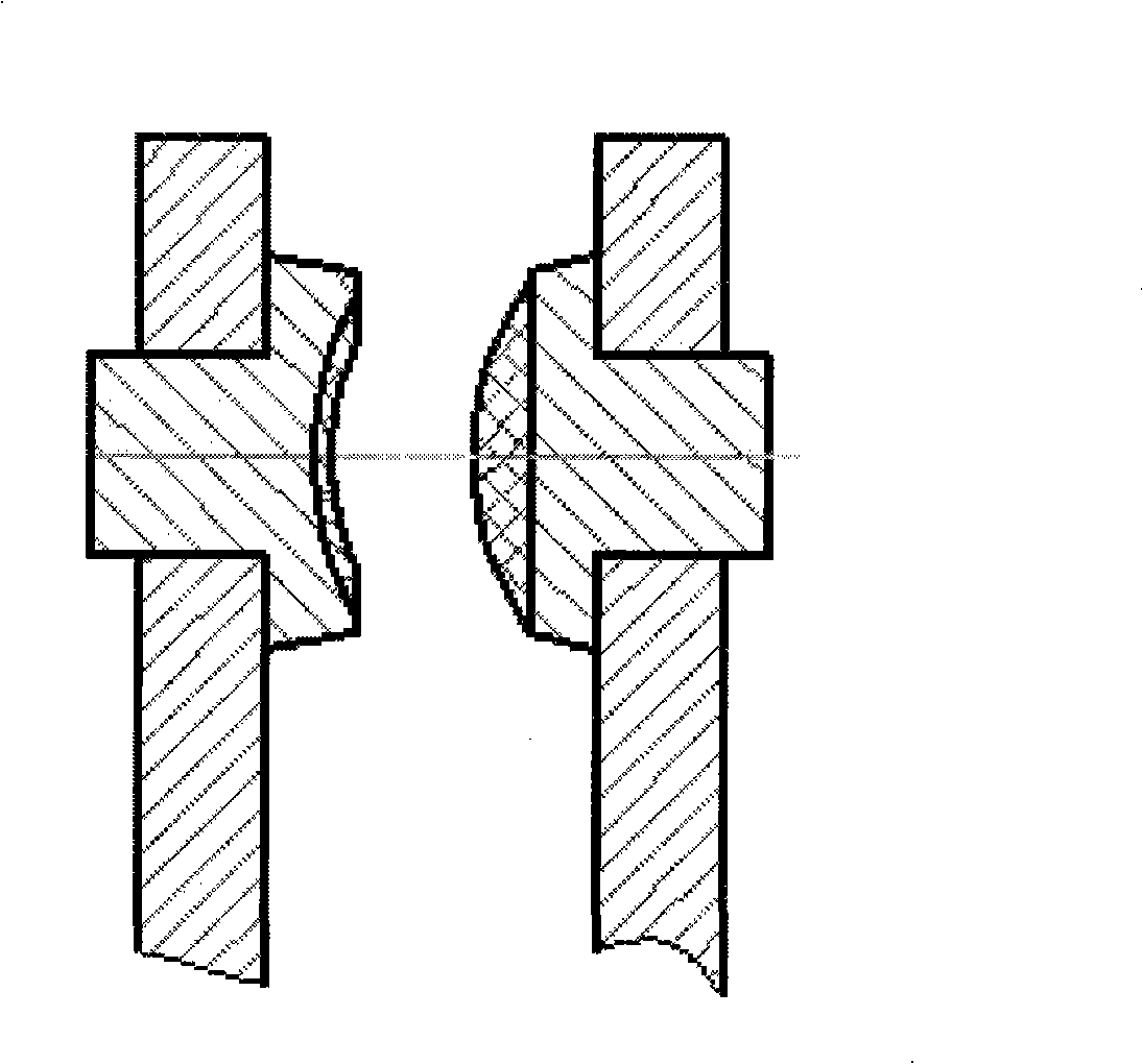
[0013] A conductive contact of the present invention includes a set of two dynamic and static contacts. The dynamic and static contacts are respectively coincident concave and convex curved surfaces. The present invention uses curved surface contact instead of plane contact or point contact.

[0014] Wherein, described curved surface is quadratic surface, and quadratic surface refers to all graphics corresponding to tern...


PUM


Abstract

The invention relates to a conductive contact, in particular to a zigzag secondary camber conductive contact used for switches, relays and contactors, comprising a group of two contacts: a movable contact and a fixed contact; the movable contact and the fixed contact are respectively a concave camber and a convex camber which are coincident to each other; the invention uses the curve contact to replace a planar contact or point contact, solves the problems that the contact area of the conductive contact is extremely finite and the contact state is unstable, and overcomes the shortages that the existing conductive contact technique and product have weak current passing capability and the contacts are easy to be burned.

Description

technical field [0001] The invention relates to a conductive contact, in particular to a quadric surface conductive contact used for concave and convex matching on switches, relays and contactors. Background technique [0002] No matter what the material of the traditional conductive contact is, its shape is two spheres facing each other, or two planes facing each other, or one sphere facing one plane. Regardless of whether the spherical surface is opposite, the plane is opposite, or the spherical surface is opposite to the plane, the contact area is very limited. The limited contact area causes the contact resistance to increase, which hinders the passage of large currents, and the heat generated increases and accumulates. The ability to pass current is the most important indicator of a conductive contact, and the contact of a small area is the fatal point that affects this indicator. From the point of view of systems engineering and control theory, this traditional conta...

Claims


Application Information

Patent Timeline
Patent Type & Authority Applications(China)
IPC IPC(8): H01H1/06H01H1/14
Inventor 李健全陈挺刘烈闯
Owner 李健全
Learn More