
Data relaying method for OFDM system and relaying station

A data relay, orthogonal frequency division technology, applied in multi-frequency code systems, diversity/multi-antenna systems, radio relay systems, etc., can solve the problem of poor channel quality, can not improve system transmission capacity, R→D link Problems such as large information loss, to achieve the effect of improving performance

Inactive Publication Date: 2009-04-01
ZTE CORP
View PDF0 Cites 32 Cited by
  • Summary
  • Abstract
  • Description
  • Claims
  • Application Information

AI Technical Summary

Problems solved by technology

Although resource scheduling through the network can allocate the same subcarrier group to the S→R link and the R→D link, there is a sequence in the time domain between the S→R link and the R→D link , and due to the different locations, the channel conditions between the same subcarriers between the S→R link and the R→D link are also not the same. The subcarriers with better signal quality in the carrier group have very poor channel quality in the R→D link, and vice versa
That is to say, the subcarriers with relatively high transmission capacity in the S→R link may be coupled to the subcarriers with relatively poor transmission capacity in the R→D link, which will lead to the loss of information in the R→D link. Big
Although it is also possible to couple subcarriers with relatively poor channel quality in the S→R link to subcarriers with relatively good channel quality in the R→D link, since the coding and modulation methods have not changed, this cannot improve the overall system performance. transmission capacity

Method used


Image

  • Data relaying method for OFDM system and relaying station
  • Data relaying method for OFDM system and relaying station
  • Data relaying method for OFDM system and relaying station

Examples


Embodiment 1

[0044] Embodiment 1 is a data relay method based on MIMO OFDM system and its relay station.

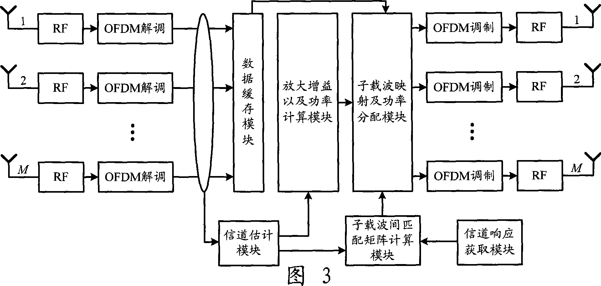
[0045] figure 2 Shown is a relay system based on MIMO OFDM, the source node S is a base station or user terminal, which is configured with N transmitting antennas, the relay node R is a wireless relay station, and it is configured with M antennas, and the destination node D is a user terminal Or a base station, which is configured with K antennas. Nodes S, R, and D are all in a frequency-selective fading channel environment, and the subcarrier group resources allocated by the network to the S→R link are exactly the same as the subcarrier resources of the R→D link, all of which are B subcarrier groups. Each subcarrier group includes K subcarriers, and in this embodiment, B=2 and K=6.

[0046] Figure 3 is figure 2 The structure schematic diagram of the relay station in the shown system structure, the relay station includes an OFDM demodulation module, an OFDM modulation module, a d...


PUM


Abstract

The invention discloses a data relay method of an orthogonal frequency division multiplexing (OFDM) system which belongs to the wireless relay technical field of a wireless mobile communication system. A relay node in the method receives signals sent by a source node, caches the data information after OFDM demodulation, estimates the channel response of the link from the source node to a relay node, and then obtains the channel response of the link from the relay node to a destination node; a relay station determines the subcarrier coupling matrix in each subcarrier group according to the channel response of the links from the source node to the relay node and from the relay node to the destination node, and simultaneously estimates gain coefficient and transmitted power; and then the relay station maps the symbol on each subcarrier in the link from the cached source node to the relay node onto corresponding subcarrier in the link from the coupled relay node to the destination node according to the coupling relation of the subcarrier, allocates the power, then carries out the OFDM modulation and finally sends the symbol to the destination node. The invention improves the performance of the entire system.

Description

technical field [0001] The invention belongs to the technical field of wireless relay in a wireless mobile communication system, and in particular relates to a data relay method and a relay station of an Orthogonal Frequency Division Multiplexing (OFDM) system. Background technique [0002] With the commercialization of 3G systems, B3G / 4G technologies with higher speed, higher spectrum efficiency, higher coverage and stronger service support capabilities have entered the standardization stage. The International Telecommunication Union ITU plans to complete B3G spectrum planning in 2007 , completed the main standard in 2010, started commercial use in 2012, and put it into commercial use on a large scale after 2015. B3G / 4G requires that the transmission rate can reach 1Gbps, and the required spectrum is at least 100MHz. It is difficult to find such broadband spectrum requirements in existing frequency bands, so a higher frequency band, such as 5GHz or 6GHz, needs to be alloca...

Claims


Application Information

Patent Timeline
IPC IPC(8): H04L27/26H04B7/14H04B7/04H04B7/005
Inventor 蒋小奎
Owner ZTE CORP
Learn More