
Ice making machine

An ice maker and ice bucket technology, which is applied in the directions of ice making, ice making, lighting and heating equipment, etc., can solve the problems of the ice maker being blocked, the motor power is large, dripping, etc., so as to reduce the probability of blocking the ice outlet pipe. , Simple structure, reliable work effect

Inactive Publication Date: 2009-04-01
应辉
View PDF1 Cites 6 Cited by
  • Summary
  • Abstract
  • Description
  • Claims
  • Application Information

AI Technical Summary

Problems solved by technology

[0003] 1. Since the above-mentioned ice-making and ice-crushing devices are equipped with a figure-eight shovel that cooperates with the reamer, in order to make the ice flow smoothly, the power of the motor must be relatively large, so that the above-mentioned structure is not suitable for small ice machines.
[0004] 2. Since the ice outlet of the above-mentioned ice making and ice crushing device can continuously output crushed ice, when the crushed ice is transported to the straight pipe-shaped ice outlet, it will continue to freeze and harden due to low temperature, and the crushed ice will easily block the ice output pipe, causing the ice maker to block and not function properly
When the crushed ice in the ice outlet tube melts, the ice water will drip from the ice receiving point, which makes the use of the ice making and crushing ice device very inconvenient
[0005] 3. Since the above-mentioned ice making and ice crushing devices have no detection device for motor obstruction, the stability of the ice making and ice crushing devices is not ideal

Method used


Image

  • Ice making machine
  • Ice making machine
  • Ice making machine

Examples


Embodiment Construction

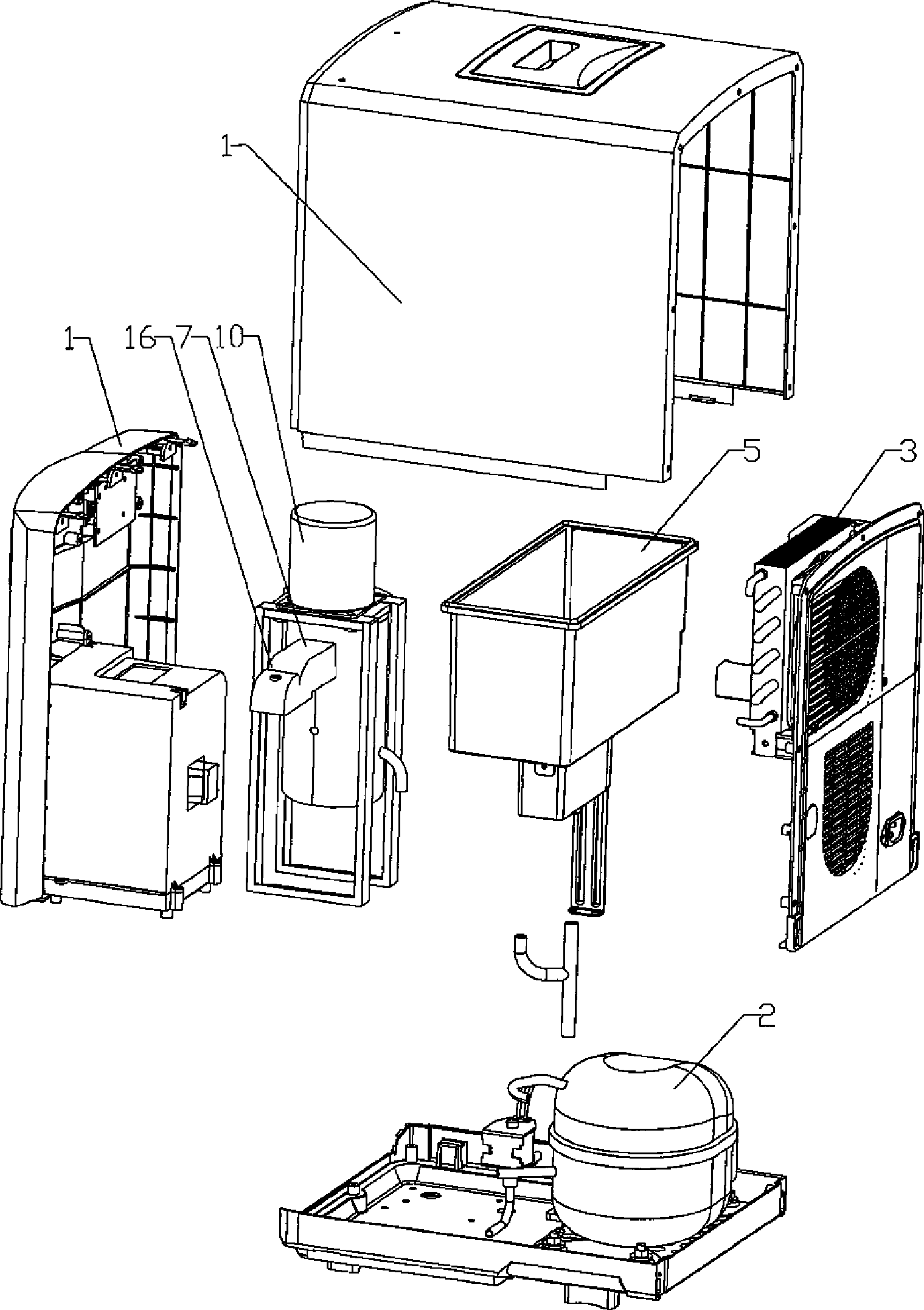
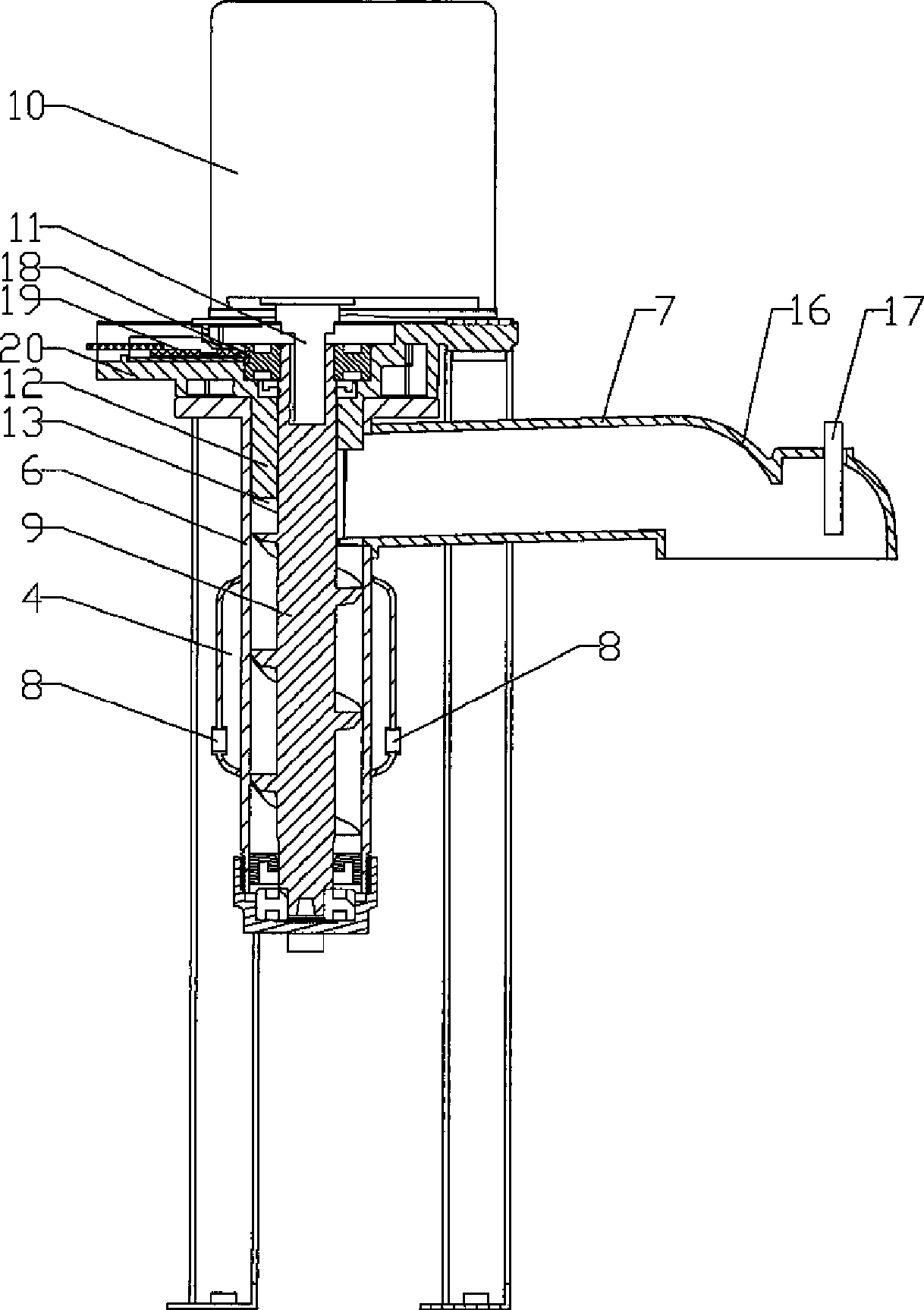
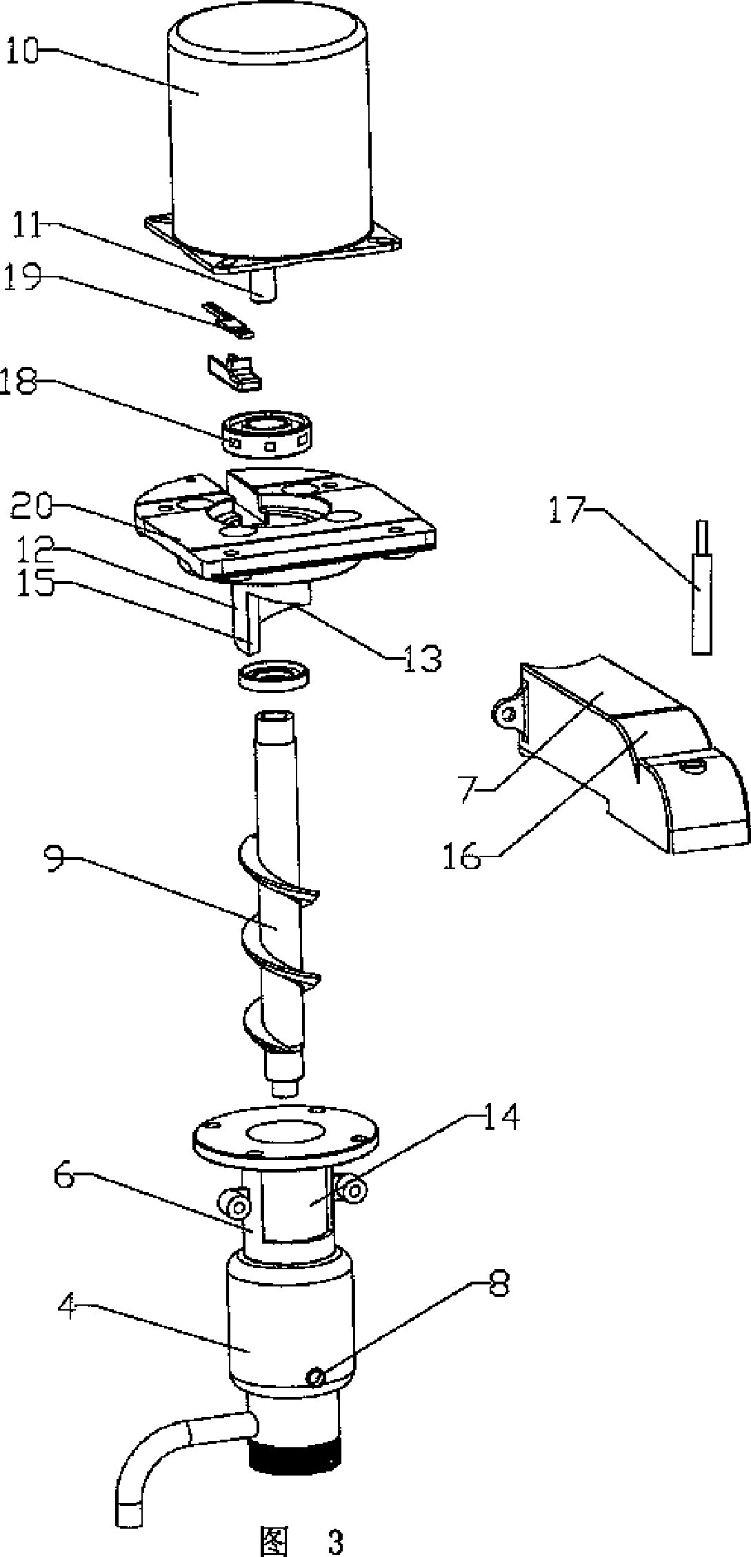
[0019] combine figure 1 , figure 2 , as shown in Figure 3: a refrigeration system is provided in the casing 1 of the ice maker of the present embodiment, and the refrigeration system includes: a compressor 2, a condenser 3, an evaporator 4 and corresponding pipelines; a water tank is provided in the water supply system 5. The control circuit controls the operation of each mechanism; the ice-making mechanism is equipped with an ice-making barrel body 6, and the ice-making barrel body is connected with a water inlet port and an ice outlet pipe 7 connected with the barrel body cavity, and the evaporator 4 is located in the system. Outside the ice bucket, the refrigerant inlet and outlet pipes 8 of the evaporator are connected to the refrigeration system pipeline of the ice maker; a reamer 9 is provided in the ice crushing mechanism, and the reamer is rotatably placed in the ice bucket body 6, and its The upper and lower ends form a seal with the upper and lower parts of the ice...


PUM


Abstract

The invention relates to an ice maker, the ice making mechanism of which is provided with an ice-making barrel body. A water inlet and an ice outlet pipe which are communicated with the cavity of the barrel body are arranged on the ice making barrel in a connection way; and an evaporator is arranged outside the ice-making barrel body. An ice-crushing mechanism is provided with a reamer which is rotatably and perpendicularly positioned inside the ice-making barrel body with the upper end and the lower end of the reamer forming sealing together with the upper part and the lower part of the ice-making barrel body. The ice maker is provided with a reversible reduction synchromotor with the output shaft being coaxially connected with the reamer. The ice-making barrel body is provided with a shovel plate that can be passed through by the reamer. The shovel plate is provided with a helical arc segment and an upright ice-blocking face which is arranged at an ice outlet. As the shovel plate is provided with the upright ice-blocking face at the ice outlet, the ice squeezed by the screwing of the reamer can be blocked by the ice-blocking face and then the ice is squeezed to the ice outlet, therefore the exiting of ice can be achieved. Simultaneously, the upright ice-blocking face can also achieve the exiting of ice reliably when the motor power is reduced.

Description

technical field [0001] The present invention relates to an ice maker. Background technique [0002] With the improvement of living standards, more and more families start to use ice machines to make ice. No. 03221488.X just proposed " the ice making of ice maker, crushing ice device " just as Chinese patent No. 03221488.X. In this technical proposal, the ice-making and ice-crushing devices include an ice-making mechanism and an ice-crushing mechanism, and the ice-making mechanism includes an ice-making bucket body, and the ice-making bucket body is connected with a water inlet communicating with the bucket body cavity. Interface and ice outlet, an evaporator, set outside the ice bucket, the refrigerant inlet and outlet pipes of the evaporator are connected with the refrigeration system pipeline of the ice maker; the ice crushing mechanism is a reamer, The reamer is rotatably placed vertically in the ice-making bucket body, and its upper and lower ends form a seal with the ...

Claims


Application Information

Patent Timeline
Patent Type & Authority Applications(China)
IPC IPC(8): F25C1/00
Inventor 应辉
Owner 应辉
Learn More