Well drilling gas injection joint and use method thereof

A drilling and gas injection technology, applied in drilling equipment, drill pipe, drill pipe, etc., can solve the problems of complex construction, high cost and high risk, achieve good gas injection effect, reduce pressure, and overcome the effects of complex process

Active Publication Date: 2009-04-01
PETROCHINA CO LTD
View PDF0 Cites 4 Cited by
  • Summary
  • Abstract
  • Description
  • Claims
  • Application Information

AI Technical Summary

Problems solved by technology

Overcoming the conventional gas injection drilling technology single wellbore gas injection mode is limited to vertical wells, limiting the use of pulse measurement while drilling tool MWD; overcoming the double wellbore gas injection mode requires an additional layer of casing and at least one packer, resulting in complex construction, High risk and high cost

Method used


Image

  • Well drilling gas injection joint and use method thereof
  • Well drilling gas injection joint and use method thereof
  • Well drilling gas injection joint and use method thereof

Examples


Embodiment 1

[0035] Embodiment 1: Taking a drilling gas injection joint with an inner diameter of 142.08 mm and an outer diameter of 153.67 mm as an example, the present invention will be further described in detail.

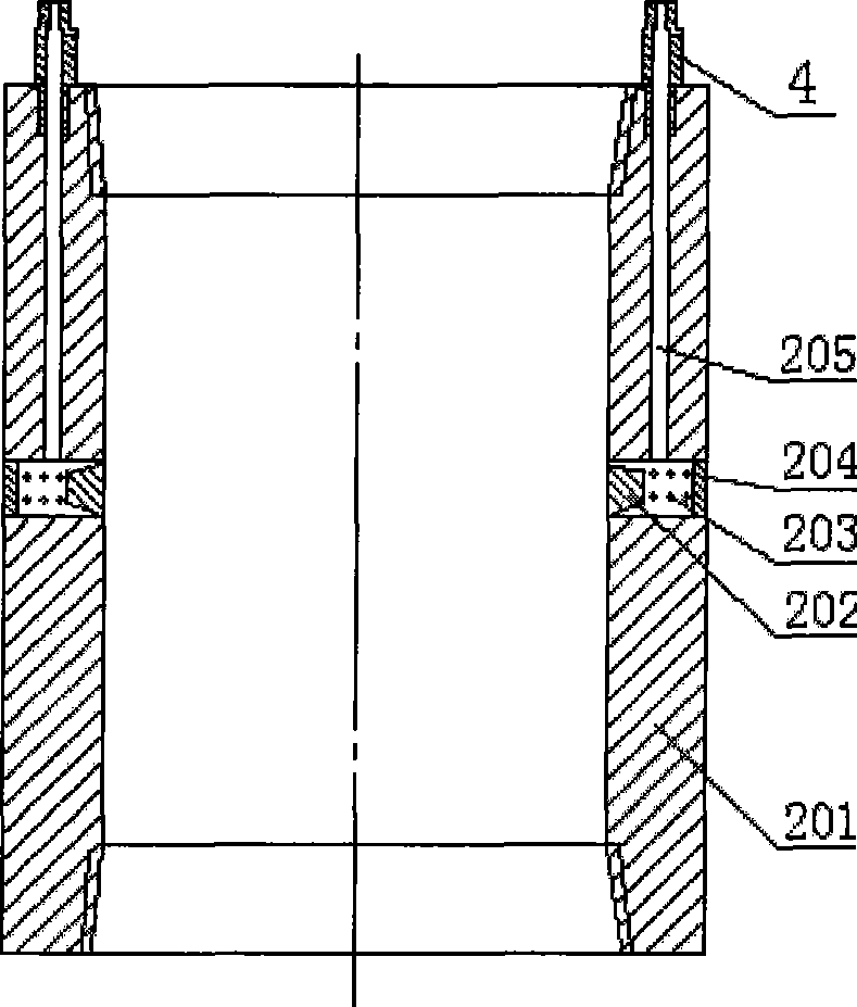
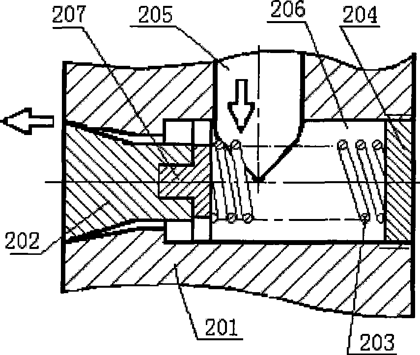
[0036] refer to figure 2. The drilling gas injection joint includes a body 201 , a tapered valve core 202 , a spring 203 , a plug 204 and a guide plate 207 . The body 201 is cylindrical, with an inner diameter of 142.08mm, an outer diameter of 153.67mm, and a length of 203.2mm. The steel material is J55 (API casing standard). The upper end and the lower end of the body 201 are provided with casing internal threads. The internal thread of the casing at the upper end and the lower end can be connected with the upper transition joint 6 and the lower transition joint 1 during the casing operation, the drilling gas injection joint is fixed in the middle of the casing string, and the casing string is run into the well at the same time.

[0037] Two longitudinal holes 205 are d...

Embodiment 2

[0041] Embodiment 2: Embodiment 2 is different from Embodiment 1: refer to Figure 7 . The valve core 202 is a plane valve core, and there is a gap at the edge of the plane valve core, and the high-pressure air can enter the casing through the gap. The circular hole at the inner end of the transverse hole 206 is a circular stepped hole.

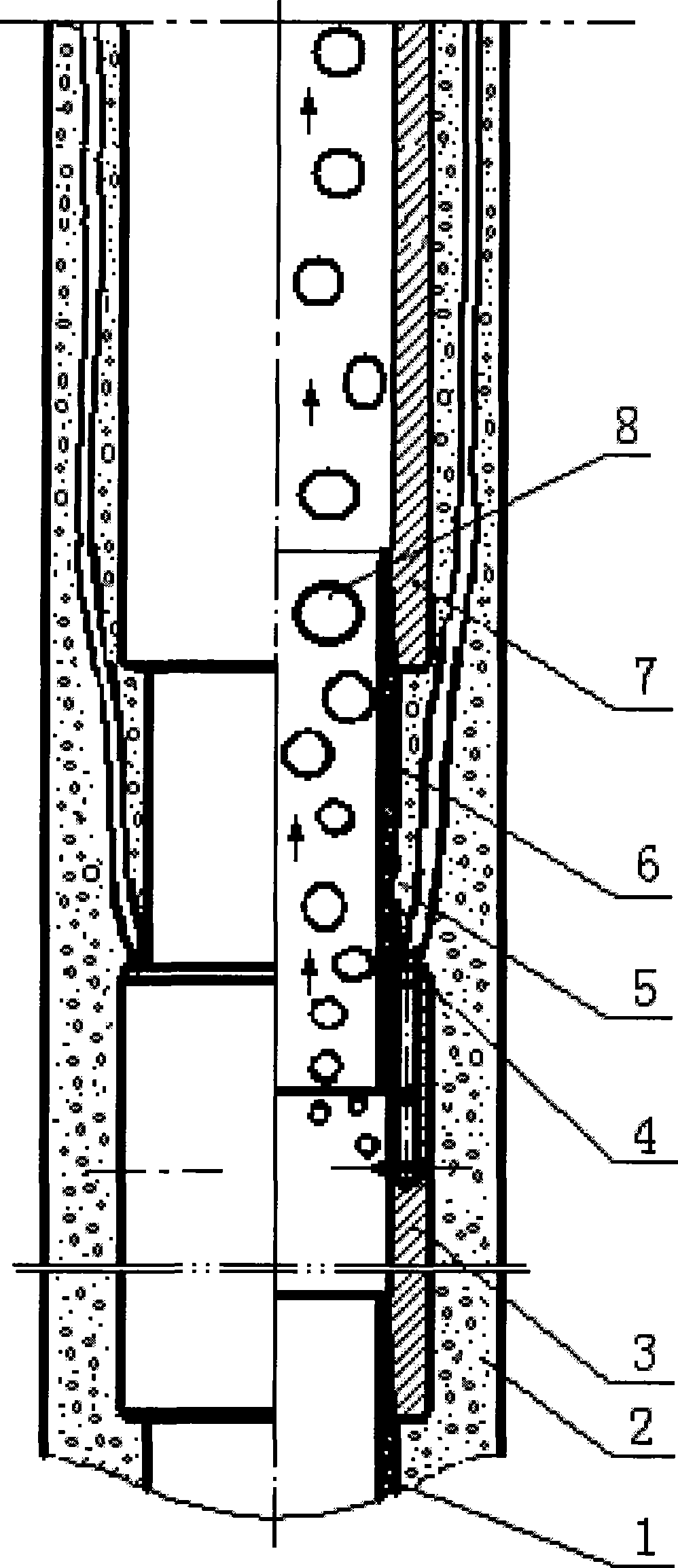
[0042] Example of using method of drilling gas injection joint: In a well with a second opening depth of 1100m, casing cementing is performed and underbalanced drilling is implemented. The working process is: see figure 1 .

[0043] A. Casing: after the second drilling is completed, the casing string with the drilling gas injection joint 3 is run in. A drilling gas injection joint 3 is connected to the middle part of the casing string. That is, the structure of the casing string is threaded from bottom to top with 400m of casing, a casing collar, a lower adapter 1, a drilling gas injection joint 3, an upper adapter 6, and a casing collar...


PUM


Abstract

The invention relates to a well drilling gas injection joint applied to the technical filed of petroleum drilling. The upper end of a main body is drilled with a longitudinal hole communicated with a horizontal hole; the inner end of the horizontal hole is a round hole and a valve core is arranged in the horizontal hole; one end of the valve core matches with the round hole at the inner end of the horizontal hole, which plays a sealing role, the other end of the valve core is fixed with a positioning disk and a spring is positioned between the positioning disk and a plug; high pressure air is transmitted to the horizontal hole through the longitudinal hole, the positioning disk is provided with a through hole, the spring is an helical extension spring and the thread of the longitudinal hole is fixed with a pipeline joint. The application process comprises the following steps of: A. putting down a bushing: the well drilling gas injection joint is connected on the pipe column of the bushing; B. well cementation; C. connection with a ground gas injection system; D. drilling construction; E. the injection of high pressure gas into the bushing; and F. stopping gas injection. The well drilling gas injection joint can effectively reduce annular hohlraum inner fluid column pressure and fulfill the purpose of safety, quick and high efficient drilling.

Description

technical field [0001] The invention relates to the technical field of oil drilling, in particular to a casing joint which is connected in the middle of the casing and fixed on the well wall together with the casing, and which can perform annular gas injection. Background technique [0002] Conventional gas injection drilling technology mainly adopts two methods: drill string gas injection and annular gas injection. [0003] Drill string gas injection uses the center of the drill string to inject gas directly to the bottom of the well. Although it does not require additional downhole equipment and the operation process is relatively simple, it limits the use of the pulse measurement-while-drilling tool MWD. [0004] There are two main methods for annular gas injection, one is to use a set of concentric strings. The concentric pipe string is to run a layer of casing with a slightly smaller outer diameter between the wellbore casing and the drill string. The bottom between th...

Claims


Application Information

Patent Timeline
Patent Type & Authority Applications(China)
IPC IPC(8): E21B21/16E21B17/08
Inventor 鲜保安赵庆波孙平鲍清英张义张继东李安启
Owner PETROCHINA CO LTD
Why Eureka
Try Eureka