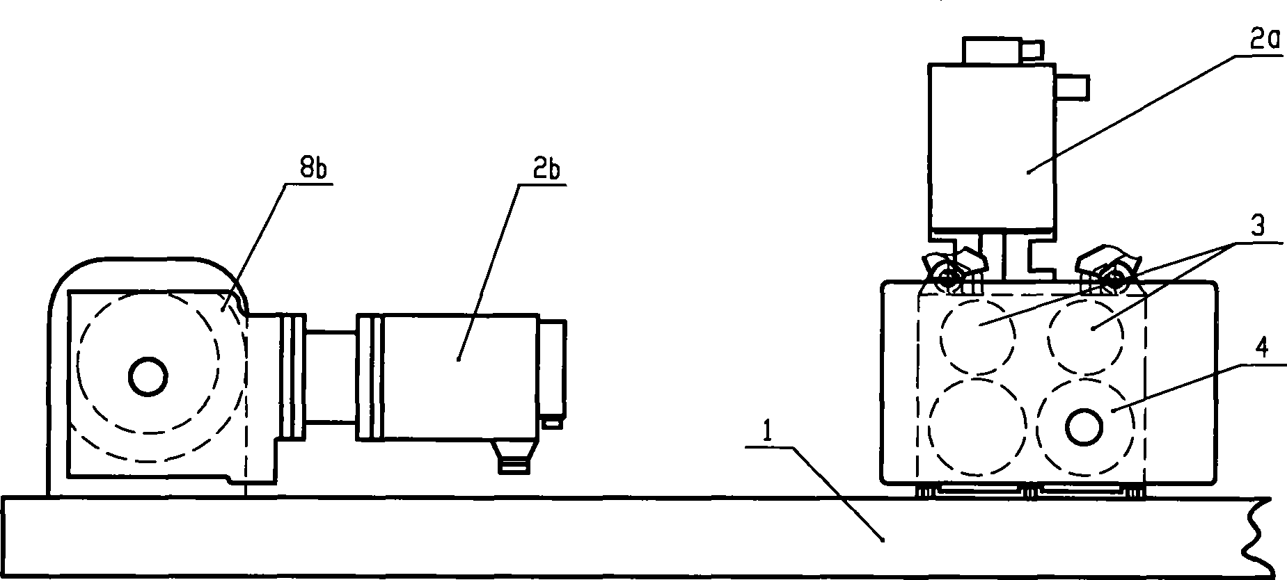
Steel-bar automatic hoop bender with synchronous belt drive mechanism
A technology of synchronous belt drive and hoop bending machine, applied in the field of automatic steel bar hoop bending machine, can solve the problems of zero drift instability of the system, large moment of inertia of the reducer, high maintenance cost, etc., and achieve cost and noise reduction, and reasonable internal layout. , the effect of reducing the outline size
- Summary
- Abstract
- Description
- Claims
- Application Information
AI Technical Summary
Problems solved by technology
Method used
Image
Examples
Embodiment 1
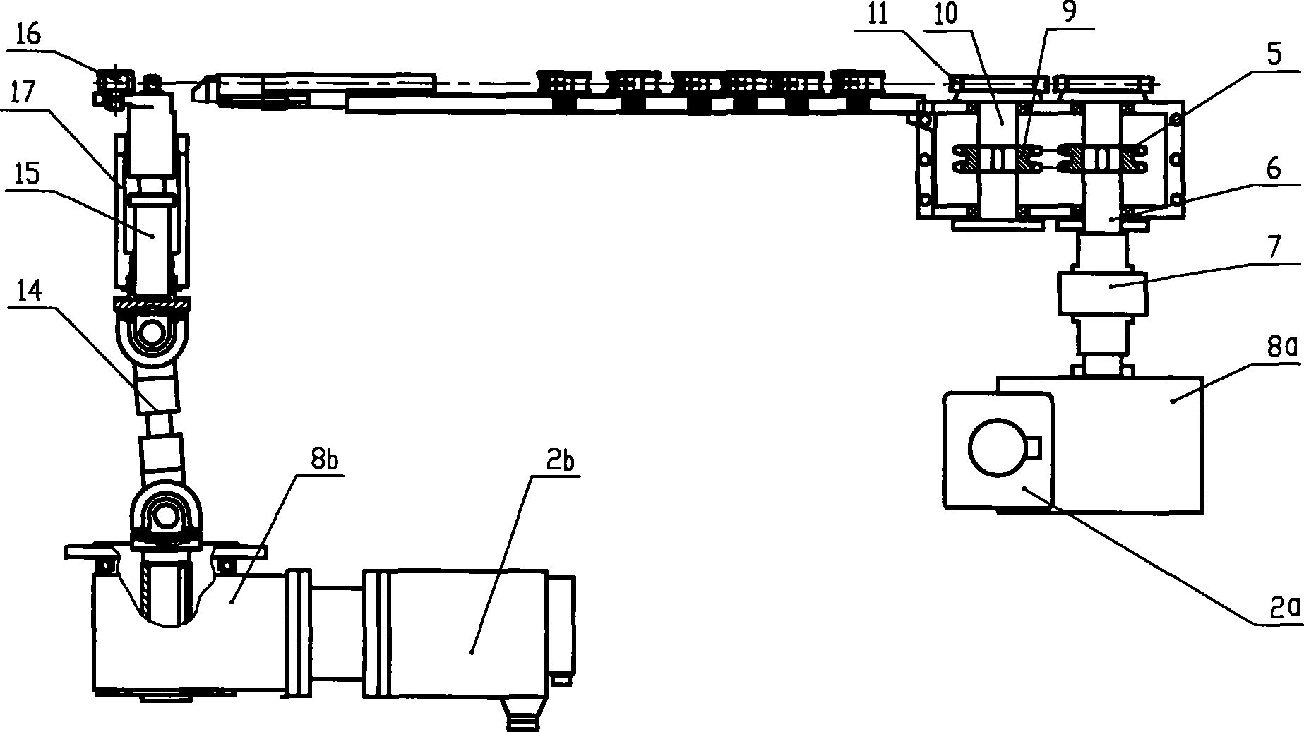
[0029] Embodiment 1 provides a structure in which the synchronous belt transmission mechanism is arranged in the bending mechanism and the input shaft is a universal joint.
[0030] Figure 4 yes image 3 The top view shows that the input shaft in the bending mechanism of Embodiment 1 of the present invention is a universal joint.
[0031] Such as Figure 4 As shown, the input shaft in the bending mechanism is a universal joint 14, and the input end of the universal joint 14 is installed in the inner hole of the driven pulley 22b of the synchronous belt transmission mechanism 20, and the universal joint 14 The output end is connected to one end of the bending main shaft 15, and the other end of the bending main shaft 15 is connected to the bending shaft 16.
Embodiment 2
[0032] Embodiment 2 provides a structure in which the synchronous belt transmission mechanism is arranged in the bending mechanism and the input shaft is the inner spline sleeve of the pulley.
[0033] Figure 5 yes image 3 The top view shows that the input shaft in the bending mechanism of Embodiment 2 of the present invention is a pulley inner spline bushing.
[0034] Such as Figure 5 As shown, the input shaft in the bending mechanism is the pulley inner spline bushing 12, and the outer diameter of one end of the pulley inner spline bushing 12 is installed in the inner hole of the driven pulley 22b of the synchronous belt transmission mechanism 20, The spline inner hole at the other end of the pulley inner spline shaft sleeve 12 is connected to one end of the spline bending main shaft 13; the other end of the spline bending main shaft 13 is connected to the bending shaft 16; the pulley inner spline shaft sleeve 12 is set In the inner hole of the bending support sleeve 1...
PUM
 Abstract
Description
Claims
Application Information
 - R&D Engineer
- R&D Manager
- IP Professional
- Industry Leading Data Capabilities
- Powerful AI technology
- Patent DNA Extraction
Browse by: Latest US Patents, China's latest patents, Technical Efficacy Thesaurus, Application Domain, Technology Topic, Popular Technical Reports.
© 2024 PatSnap. All rights reserved.Legal|Privacy policy|Modern Slavery Act Transparency Statement|Sitemap|About US| Contact US: help@patsnap.com


