
Slot forming method

A trench and pattern technology, applied in electrical components, semiconductor/solid-state device manufacturing, circuits, etc., can solve the problems of prolonged time, prolonged production cycle, low removal efficiency, etc., to improve electrical performance, improve formation quality, operation easy effect

Inactive Publication Date: 2009-03-25
SEMICON MFG INT (SHANGHAI) CORP
View PDF1 Cites 26 Cited by
  • Summary
  • Abstract
  • Description
  • Claims
  • Application Information

AI Technical Summary

Problems solved by technology

At present, there is a problem of great concern in the formation process of the trench used to form the metal connection: the removal of the remaining photoresist and polymer after etching
However, in the first step of the ashing process, most of the remaining photoresist and polymer need to be removed at low temperature without bias, and the removal efficiency is low, which prolongs the time required for the entire ashing process. time, which lengthens the production cycle and is not suitable for popularization and application in actual production

Method used


Image

  • Slot forming method
  • Slot forming method
  • Slot forming method

Examples


Embodiment Construction

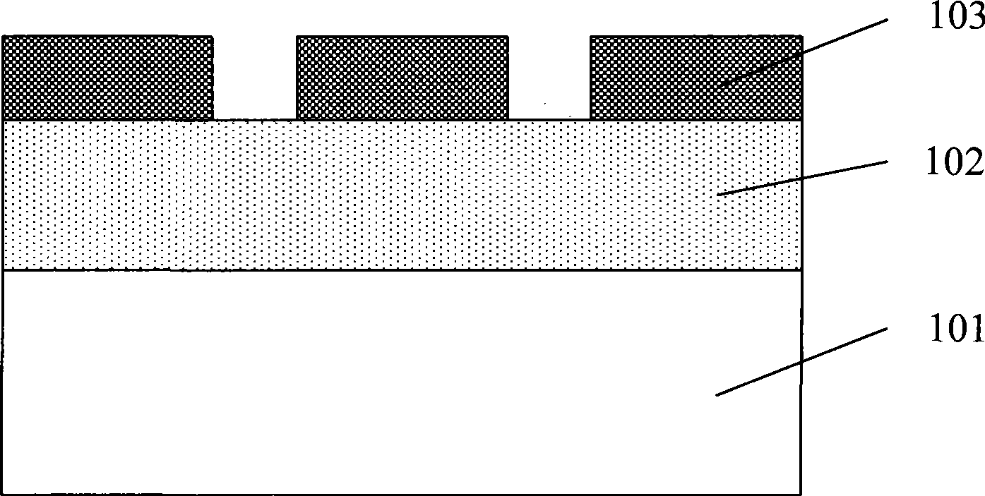
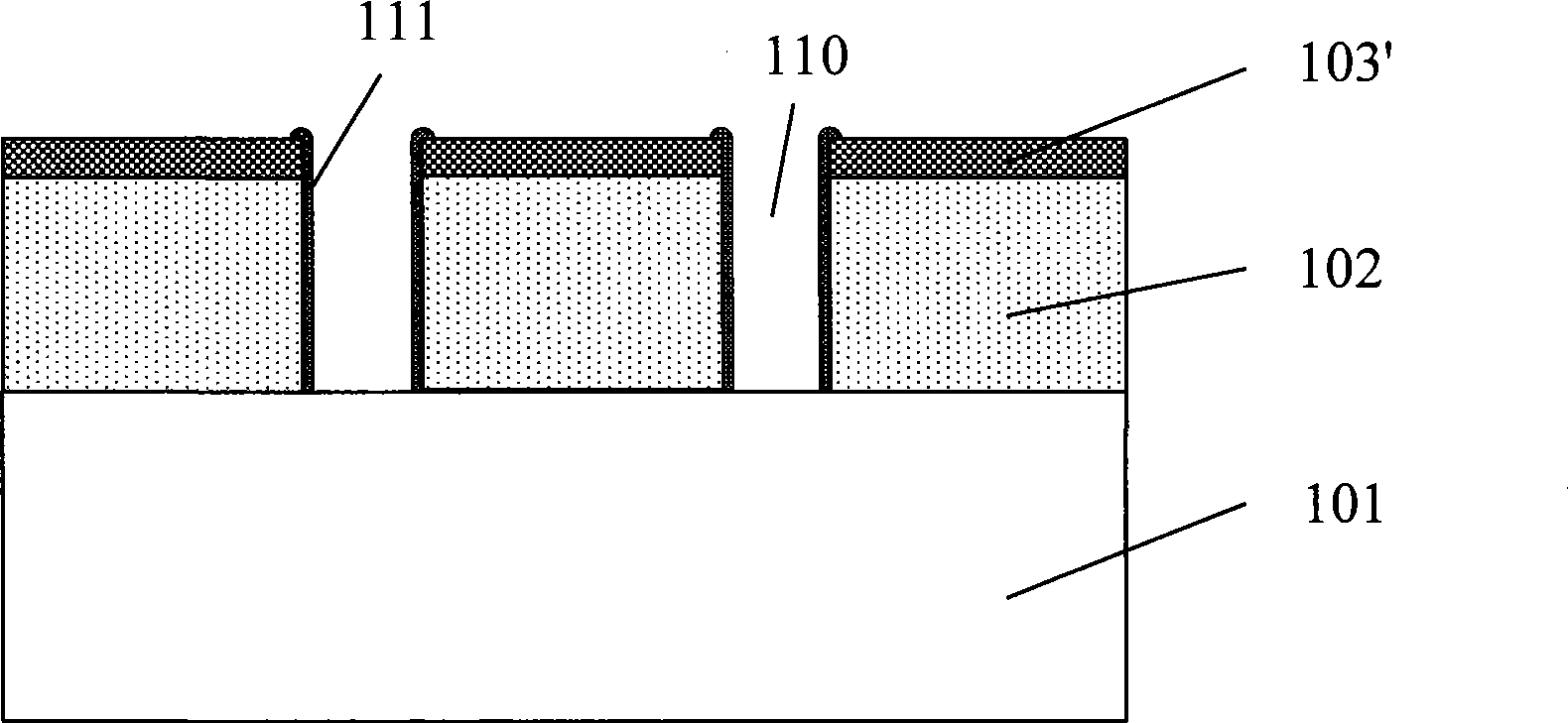
[0043] In order to make the above objects, features and advantages of the present invention more comprehensible, specific implementations of the present invention will be described in detail below in conjunction with the accompanying drawings.

[0044] The processing method of the present invention can be widely used in various fields, and can utilize many suitable materials to make, and the following is to illustrate by specific embodiment, certainly the present invention is not limited to this specific embodiment, in this field Common replacements known to those of ordinary skill undoubtedly fall within the protection scope of the present invention.

[0045] Secondly, the present invention is described in detail using schematic diagrams. When describing the embodiments of the present invention in detail, for the convenience of explanation, the cross-sectional view showing the device structure will not be partially enlarged according to the general scale, which should not be u...


PUM

PropertyMeasurementUnit
Thicknessaaaaaaaaaa

Abstract

The invention discloses a method for forming a groove, which includes the steps as follows: a substrate is provided, and an etching stop layer and a medium layer are arranged on the substrate; a groove figure is defined on the medium layer; a groove is formed by etching; the substrate is subjected to high temperature incineration treatment; and a plasma etching method is used for removing the etching stop layer and the residual photoresist and polymer particulates at the same time. Under the condition that no excess processing step is added, the method for forming the groove not only keeps the good shape of the side wall of the groove, but also cleans the residual photoresist and polymer particulates away and efficiently improves the electrical property of a device.

Description

technical field [0001] The invention relates to the technical field of semiconductor manufacturing, in particular to a method for forming a trench. Background technique [0002] The semiconductor manufacturing process is a planar manufacturing process that forms a large number of various types of complex devices on the same substrate and interconnects them to have complete electronic functions. In this manufacturing process, it is often necessary to form a large number of trenches on the substrate, which can be filled with metal to form metal connections. At present, there is a problem of great concern in the formation process of the trench used to form the metal connection: the removal of the remaining photoresist and polymer after etching. [0003] There are two main methods for removing residual photoresist and polymer after traditional etching, one is the method of ashing at low temperature, which can obtain better residue removal effect, However, it will cause chamfer...

Claims


Application Information

Patent Timeline
IPC IPC(8): H01L21/00H01L21/02H01L21/308H01L21/76H01L21/768
Inventor 周鸣沈满华
Owner SEMICON MFG INT (SHANGHAI) CORP
Learn More