
Electronic public transport stop board realizing relay type communication by using ISM frequency band

A bus stop sign and stop sign technology, applied in electrical components, traffic control systems, traffic control systems of road vehicles, etc., can solve the problems of waste of GPS positioning accuracy, redundant path detours, large electromagnetic wave pollution, etc., and achieve power consumption. Province, no need for mains feed, less electromagnetic wave pollution

Inactive Publication Date: 2009-03-25
SHANGHAI SECOND POLYTECHNIC UNIVERSITY
View PDF5 Cites 6 Cited by
  • Summary
  • Abstract
  • Description
  • Claims
  • Application Information

AI Technical Summary

Problems solved by technology

Obviously, these two points also bring corresponding disadvantages: firstly, using the existing GPRS / CDMA network to transmit information and GPS positioning will inevitably generate operational communication costs; secondly, using GPS positioning to determine whether the vehicle is on the station is a waste of GPS positioning accuracy , because the bus can drive from one station to another in just a few minutes when the road is clear; finally, it uses continuous wireless calls to determine whether the vehicle is at the station, and the vehicle at the station is sent by the main console After the information is received, the station signs along the line are notified wirelessly, which wastes a lot of energy and produces large electromagnetic wave pollution, because the former wireless calls between stations are futile, and the latter realizes the vehicle stop information by the main console There is a lot of path redundancy in forwarding, because the stop sign adjacent to the stop sign that the vehicle is leaning on has to detour to get this information from the main console

Method used


Image

  • Electronic public transport stop board realizing relay type communication by using ISM frequency band

Examples


Embodiment Construction

[0014] Below in conjunction with accompanying drawing and embodiment the present invention is described in further detail, but present embodiment is not intended to limit the present invention, and every similar method of the present invention and similar changes thereof should be included in the scope of protection of the present invention.

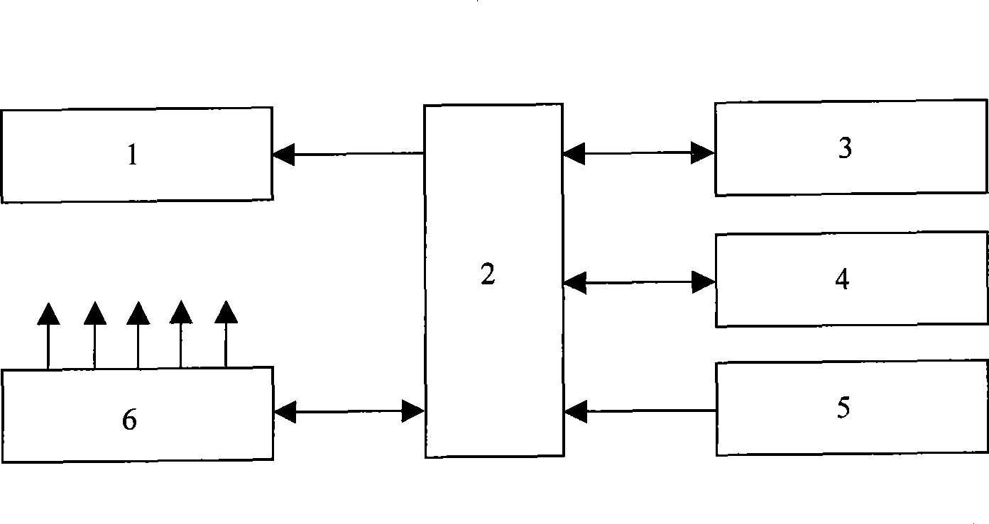
[0015] An electronic bus stop board that realizes relay communication in the ISM frequency band. The front of the stop board is the conventional station name, line number, and orderly arrangement of the station names on the line. Each station name is embedded with A light-emitting diode (LED) is used to indicate the position information of the station where the downstream vehicle is now; a circuit board is installed on the reverse side of the stop sign, and its circuit structure is as follows: figure 1 As shown, the circuit board is equipped with a microcontroller 2, a stop sign indirect force type ISM wireless communication module 3, an ...


PUM


Abstract

The invention relates to an electronic bus station board which can realize relay type communication through an ISM public frequency band. The normal station name, line numbers and orderly arranged line drawing marked with the name of each station are arranged on the front side of the board, and a light emitting diode (LED) is embedded below each station name; a circuit board is installed on the back side of the board, and a board-to-board relay type ISM wireless communication module, a board-to-arriving bus ISM wireless communication module, a bus arriving detector and an LED bus stopping position display which are arranged on the circuit board are connected with a microcontroller; and a solar panel and an accumulator module are connected with both the microcontroller and each element circuit on the circuit board. The electronic bus station board has the advantages that the fabrication cost is low, the pollution of the electromagnetic wave is small, and the feed of commercial power is not needed; not only the real-time information on the position of the coming bus is visually provided for the passengers waiting for the bus, but also the real-time efficient dispatching can be possible for the bus line management department.

Description

technical field [0001] The invention relates to an electronic bus stop board which realizes relay communication in the ISM frequency band, which is used to visually provide real-time information of the station where the vehicle is about to arrive to the city bus waiting passengers, and also to the real-time and efficient dispatching of the bus line management department offers the possibility. Background technique [0002] At present, there are mainly two types of electronic stop sign systems used for bus arrival forecast at home and abroad: [0003] 1. "GPS global positioning + GPRS / CDMA network + short-range wireless communication" program. The information transmission method of this scheme is: the vehicle determines the stop by satellite GPS positioning -> the vehicle notifies the stop sign by short-range wireless communication -> the stop sign notifies the main console via GPRS or CDMA network -> the main control station sends it via GPRS / CDMA network It will ...

Claims


Application Information

Patent Timeline
Patent Type & Authority Applications(China)
IPC IPC(8): G08G1/00G08G1/123G09F9/33H04B5/00
Inventor 杨冠群
Owner SHANGHAI SECOND POLYTECHNIC UNIVERSITY
Learn More