
Integration combustion pressure sensor for internal combustion engine

A combustion pressure and internal combustion engine technology, applied in the direction of combustion ignition, combustion methods, instruments, etc., can solve the problem that the system is susceptible to interference from external vibration and temperature changes, etc., to improve system reliability, reduce fuel consumption and pollution, and reduce external noise effect

Inactive Publication Date: 2009-03-25
刘温
View PDF31 Cites 5 Cited by
  • Summary
  • Abstract
  • Description
  • Claims
  • Application Information

AI Technical Summary

Problems solved by technology

[0006] The purpose of the present invention is to provide an integrated combustion pressure sensor for an internal combustion engine, which solves the problems in the prior art that the piezoelectric element is compressed in the entire system by preload, making the entire system susceptible to interference from external vibration and temperature changes. With the characteristics of high precision, strong anti-interference and low cost, it is a piezoelectric pressure sensor that can be integrated into existing internal combustion engine components

Method used


Image

  • Integration combustion pressure sensor for internal combustion engine
  • Integration combustion pressure sensor for internal combustion engine
  • Integration combustion pressure sensor for internal combustion engine

Examples


Embodiment Construction

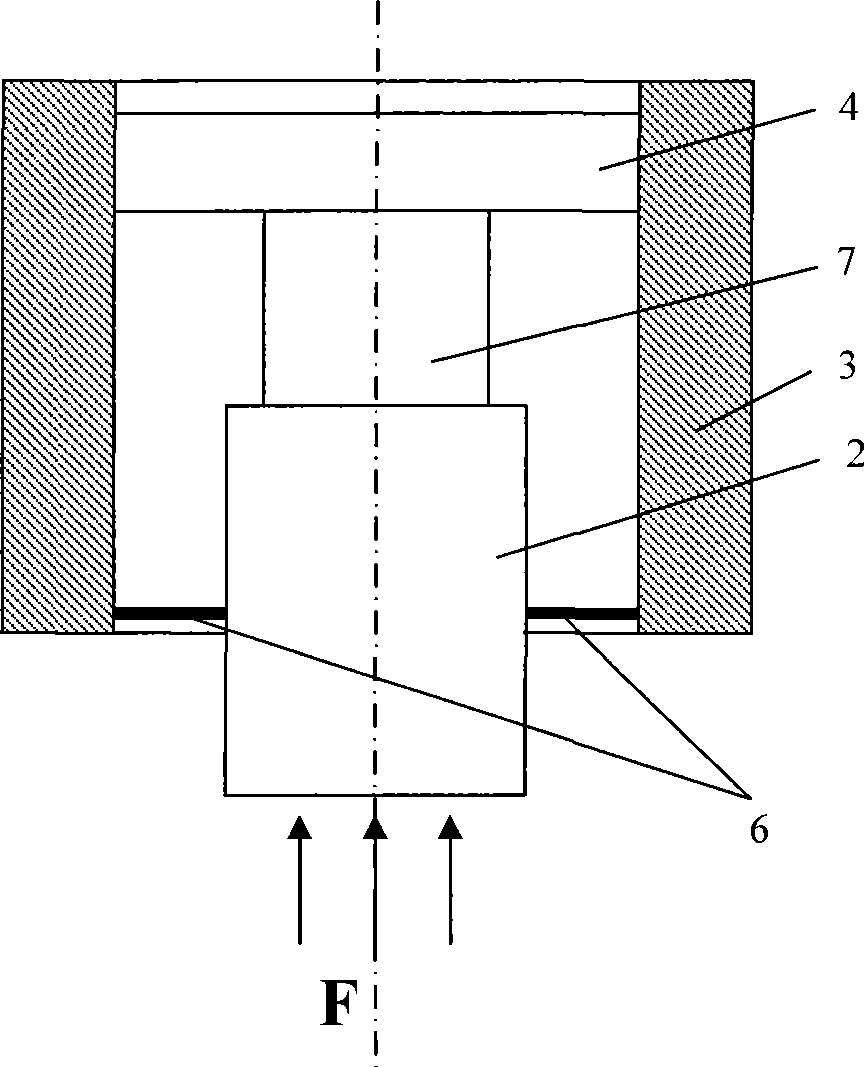
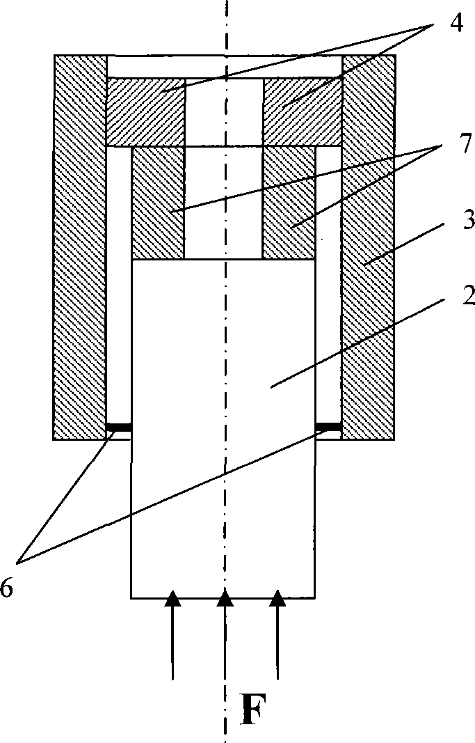
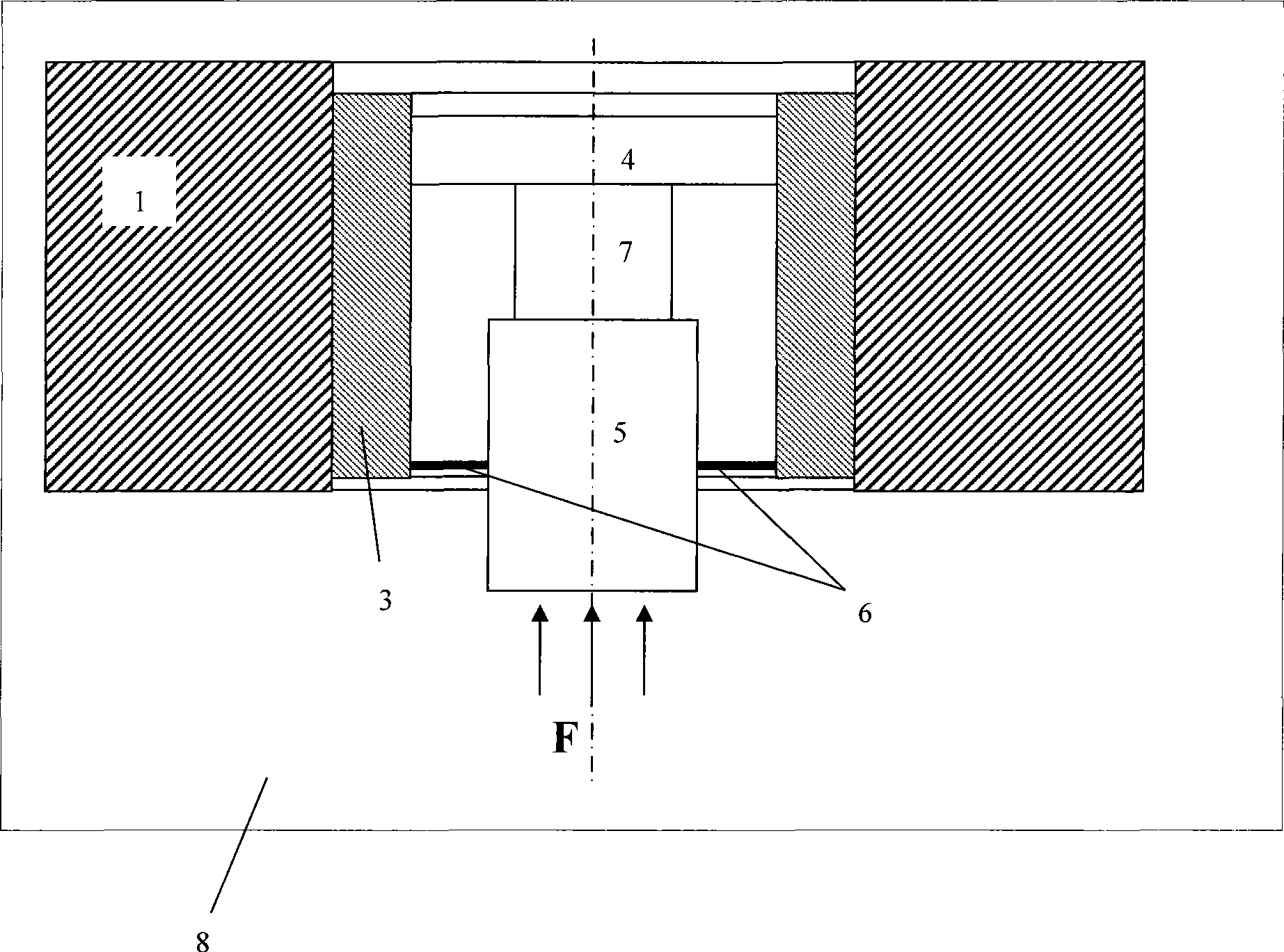
[0047] Such as Figure 1-Figure 2 As shown, the components of the integrated combustion pressure sensor of the present invention include a piezoelectric (force measuring) element 7, a rigid connection element 4, a flexible connection element 6, a housing 3, an internal combustion engine functional element 2 and other accessories such as signal transmission, signal processing, power lines, etc. One end of the piezoelectric element 7 is connected to the rigid connection element 4 by sintering or brazing or bonding, and the other end is connected to the functional element 2 of the internal combustion engine, such as a glow plug or spark plug, and the rigid connection element 4 is connected by sintering or brazing or bonding on the rigid shell 3. The functional element 2 of the internal combustion engine is connected to the shell directly or through the accessories of the functional element, such as the housing of the functional element, or other parts of the functional element t...


PUM

PropertyMeasurementUnit
Thicknessaaaaaaaaaa

Abstract

The invention belongs to the field of combustion control of internal combustion engines and sensors, and in particular relates to an integrated combustion pressure sensor for an internal combustion engine, which solves the problems that in the prior art, a piezoelectric element is firmly pressed in the whole system by a pretightening force, which causes the whole system to be affected by external vibration and temperature change and so on. The integrated combustion pressure sensor for the internal combustion engine has the characteristics of high accuracy, strong anti-jamming performance, low cost and so on, and is a pressure sensor which can be integrated into components of the prior internal combustion engine. The integrated combustion pressure sensor for the internal combustion engine consists of one or more piezoelectric force measurement elements, at least one rigid connecting element, at least one flexible connecting element, at least one internal combustion engine functional element, a shell and a plurality of accessories, wherein one end of each of the piezoelectric elements is connected to the rigid connecting element, while the other end is connected to the internal combustion engine functional element; and the rigid connecting element is connected to a rigid shell, and the internal combustion engine functional element is connected to the shell through the flexible connecting element. The integrated combustion pressure sensor for the internal combustion engine is arranged at the position of the internal combustion engine close to a combustion chamber, and is used for the measurement of combustion pressure of the internal combustion engine.

Description

Technical field: [0001] The invention belongs to the field of internal combustion engine combustion control and sensors, in particular to an integrated combustion pressure sensor for internal combustion engines. Background technique: [0002] In order to further reduce automobile energy consumption and reduce pollution, the automobile internal combustion engine control system urgently needs to measure the combustion status in real time to better control the combustion process. Among the physical parameters of the combustion process, the combustion pressure can accurately reflect the combustion process and is the most convenient to measure. [0003] The structure of modern automobile engines is extremely compact, and any change to the engine structure will affect the performance of the engine, so it is best to integrate the measurement of combustion pressure into existing components. Within the scope of existing engine technology, spark plugs for gasoline engines and glow pl...

Claims


Application Information

Patent Timeline
IPC IPC(8): G01L23/22F23Q7/00
Inventor 刘温
Owner 刘温
Learn More