Disk brake for monitoring brake positive pressure
A disc brake and positive pressure technology, applied in the direction of brake type, axial brake, hoisting device, etc., can solve the problems of large outer diameter of the small ring of the sensor, small radial size of the middle ring, and inconspicuous radial strain , to achieve wide practicability, improve reliability, and simple structure
- Summary
- Abstract
- Description
- Claims
- Application Information
AI Technical Summary
Problems solved by technology
Method used
Image
Examples
Embodiment 1
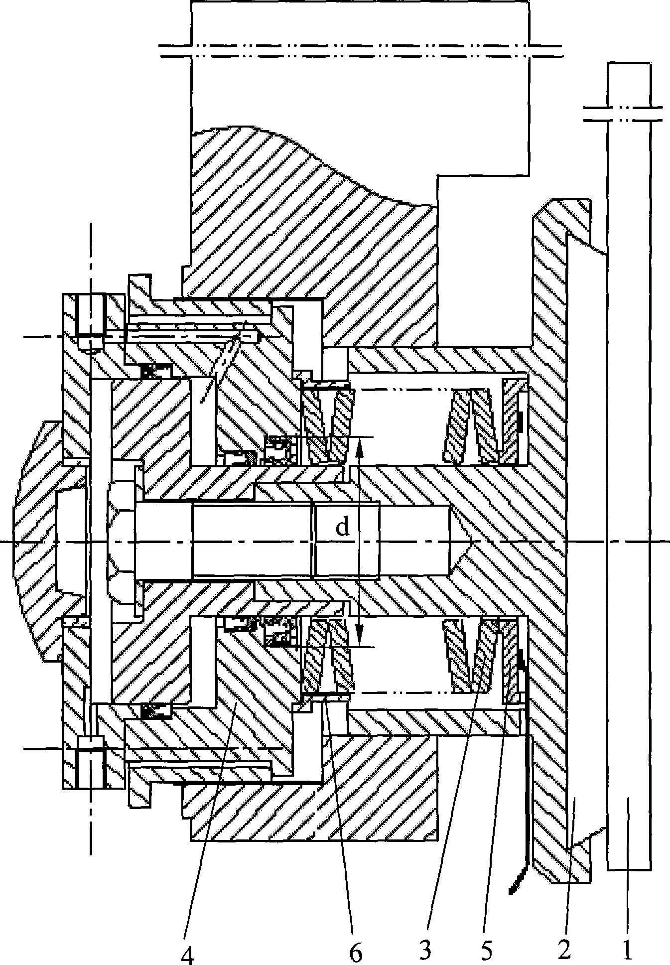
[0012] Embodiment one, figure 1 As shown, it consists of a brake disc 1, a brake shoe assembly 2 connected to the brake disc 1, a disc spring 3 arranged in the brake shoe assembly 2, and a hydraulic cylinder 4 supporting the movement of the brake shoe assembly 2. The diameter of the installation sealing ring on the hole is d, and the disc spring seat sensor 5 is arranged between the lining plate of the brake shoe assembly 2 and the disc spring 3 . The base of the disc spring seat sensor 5 is a ring strain beam 5-1 varying in thickness, such as figure 2 shown. Divided into three rings according to the thickness and stress, the small ring a is supported on the small diameter of the disc spring 3, and bears the positive braking pressure P generated by the disc spring; the large ring c is supported on the liner of the brake shoe assembly 2, and bears the liner four strain gauges 5-2 are pasted on the radial direction of the suspended intermediate ring b, and the intermediate ri...
Embodiment 2
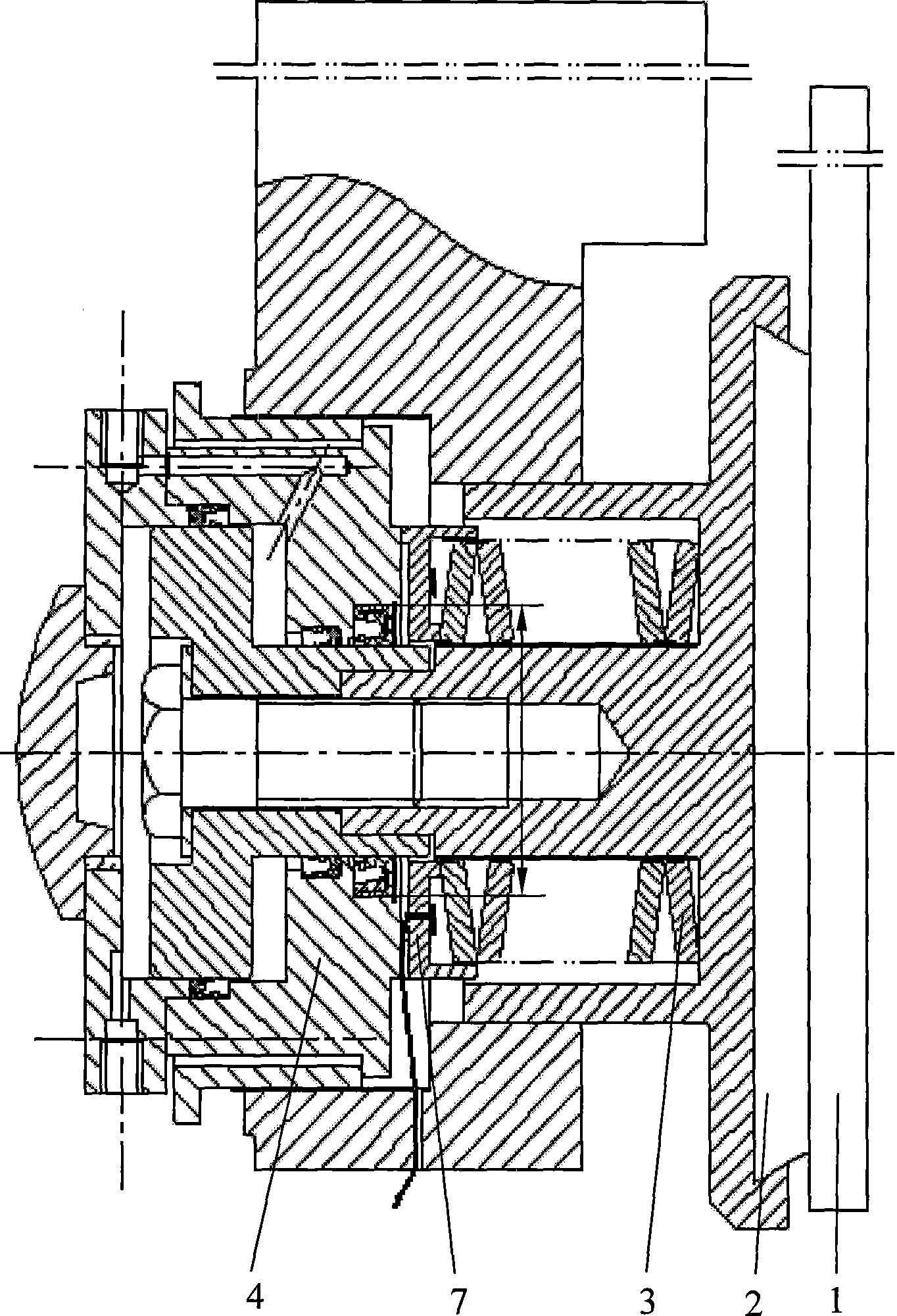
[0013] Embodiment two, image 3 As shown, the same part as the embodiment is omitted. The top of the disc spring 3 is equipped with a disc spring seat sensor 7 in contact with its small diameter, and the base of the disc spring seat sensor 7 is a ring strain beam 7-1 that varies in thickness. Figure 4 As shown, it is divided into three rings according to the thickness and force. The small ring a is supported on the small diameter of the disc spring 3, and bears the braking positive pressure P generated by the disc spring; the large ring c is supported on the hydraulic cylinder 4, avoiding the hydraulic pressure. The position hole where the diameter of the sealing ring on the cylinder is d is subjected to the support reaction force P' of the hydraulic cylinder 4; four strain gauges 7-2 are attached to the radial direction of the middle ring b, and the suspended middle ring b is under the normal pressure P The strain is generated under the action of the support reaction force ...
PUM
 Abstract
Description
Claims
Application Information
 - R&D Engineer
- R&D Manager
- IP Professional
- Industry Leading Data Capabilities
- Powerful AI technology
- Patent DNA Extraction
Browse by: Latest US Patents, China's latest patents, Technical Efficacy Thesaurus, Application Domain, Technology Topic, Popular Technical Reports.
© 2024 PatSnap. All rights reserved.Legal|Privacy policy|Modern Slavery Act Transparency Statement|Sitemap|About US| Contact US: help@patsnap.com


