Eureka AIR delivers breakthrough ideas for toughest innovation challenges, trusted by R&D personnel around the world.

Concrete electrical pole and preparation thereof

A production method and concrete technology, applied in the direction of building types, buildings, towers, etc., can solve the problems of increased construction difficulty, waste of resources and production, and increase of bending strength, so as to reduce production and construction difficulty, improve bending strength, The effect of improving the bending moment resistance

Active Publication Date: 2009-03-18
杨兴明
View PDF0 Cites 4 Cited by
  • Summary
  • Abstract
  • Description
  • Claims
  • Application Information

AI Technical Summary

Problems solved by technology

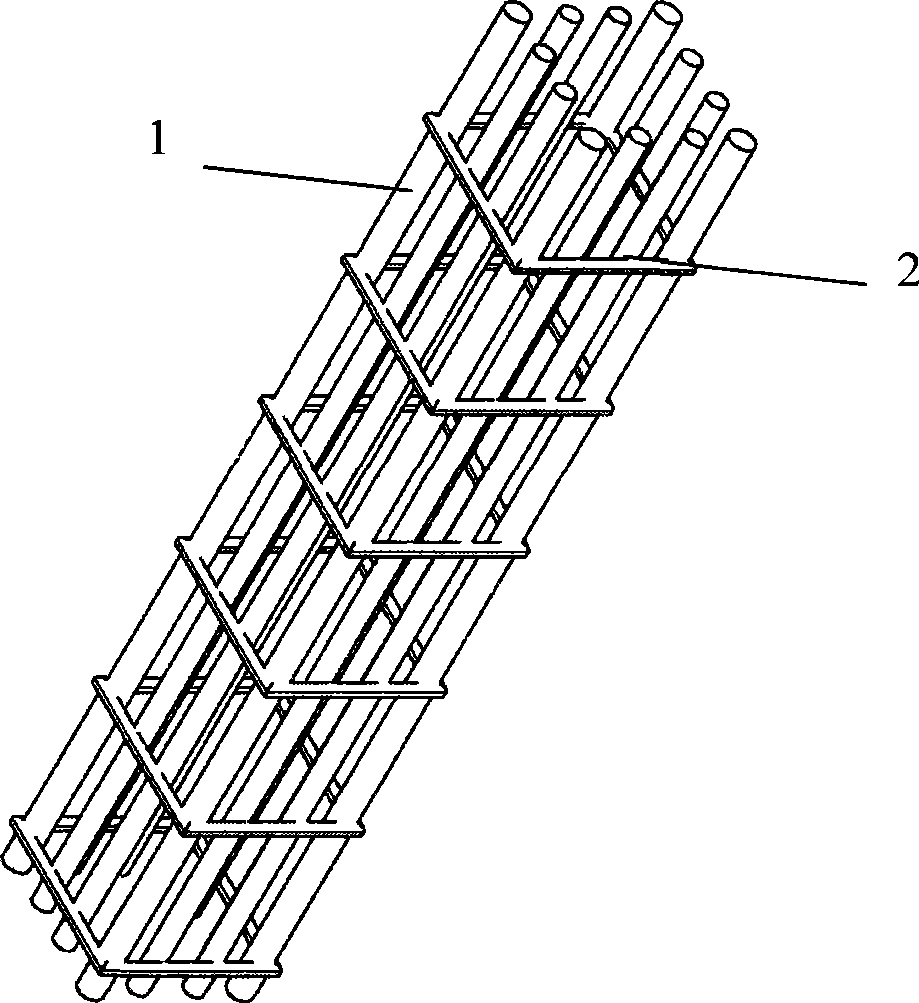
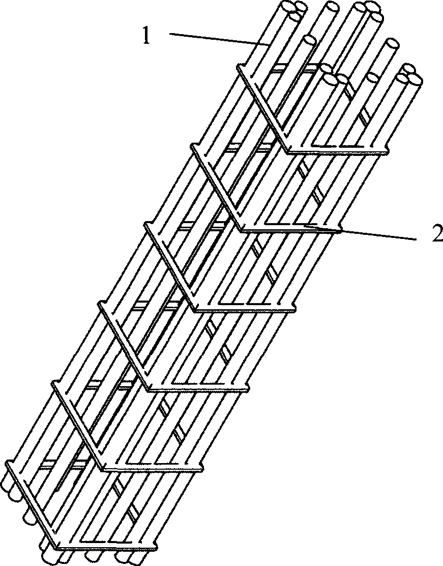
[0003] In order to solve the problems that the concrete poles in the prior art cannot effectively increase the bending strength, waste resources and increase the difficulty of production or construction, the present invention proposes a concrete pole and its manufacturing method

Method used


Image

  • Concrete electrical pole and preparation thereof
  • Concrete electrical pole and preparation thereof
  • Concrete electrical pole and preparation thereof

Examples


specific Embodiment 2

[0030] attached Figure 5 It is a structural diagram of an embodiment in which a rectangular concrete pole of the present invention uses angle steel instead of four-corner rebar straight strips to add rebar straight strips to the inner surface of the right angle of the angle steel. In the figure, 1 is a straight strip of rebar, 2 is a rectangular frame, 3 is an angle steel, and 4 is concrete. As can be seen from the figure, the present embodiment adds 1 threaded steel (attached Figure 5 1), so that the bending strength of the concrete pole can be further improved.

specific Embodiment 3

[0031] attached Figure 6 It is a structural schematic diagram of an embodiment in which a rectangular concrete pole of the present invention adopts angle steel instead of four-corner rebar straight bar skeletons and adds triangular supports between the angle steels. (for clearly showing that the triangular support figure does not draw the rebar and the triangular support on the other two sides). Among the figure, 2 is a rectangular frame, 3 is an angle steel, and 5 is a triangular support. It can be seen from the figure that the triangular support is set between two angle steels. From the stability of the triangle, it can be seen that this structure has high stability and can effectively improve the bending strength of the concrete pole skeleton, thereby effectively improving the concrete pole. Bending strength.

[0032] attached Figure 7 It is a schematic side view of an embodiment of a rectangular concrete pole of the present invention that uses angle steel instead of f...

specific Embodiment 4

[0033] attached Figure 8 It is a top view structural diagram of an embodiment of a hexagonal skeleton formed by using angle steel instead of threaded steel straight strips to form a round concrete pole of the present invention. In the figure, 1 is a straight strip of rebar, 3 is an angle steel, 4 is concrete, and 5 is a triangular support. It can be seen from the figure that in this embodiment, six angle steels are used instead of six straight strips of rebar, and they are uniformly distributed. At this time, the angle between the two sides of the angle steel is 120°.


PUM


Abstract

The invention provides a concrete pole and a manufacturing method thereof in order to solve the problems of a concrete pole in the prior art of incapability of effectively increasing the counter bending strength, resource waste, increased difficulty in production or construction and so on. The manufacturing method adopts angle steels instead of screw-threaded steel vertical bars to be a main stress supporting body, and triangular supports are arranged between the angle steels, so that the manufacturing method not only can effectively improve the counter bending strength but also can effectively reduce the weight of a metal framework of the concrete pole, and reduces the resource waste, the cost, the production and construction difficulty. Under the condition of the same counter bending moment, the weight of the framework of the concrete pole is reduced by more than 20 percent compared with the prior art, so that the manufacturing method reduces the resource waste, the cost and the production and construction difficulty, and has good economic benefit and social benefit.

Description

technical field [0001] The invention relates to a concrete electric pole and a manufacturing method thereof. Background technique [0002] Concrete poles used for power and communication cables are usually composed of metal skeleton and concrete. In the production process, usually after the metal skeleton is made first, pouring, centrifugal molding and other technologies are used to shape and solidify the concrete around the metal skeleton to form the main body of the pole. The metal skeleton of the existing concrete pole is mainly composed of threaded steel straight strips and round steel. The same shape as the cross-section of the pole, on which the rebar straight strips are fixed by welding or binding to form the skeleton of the concrete pole. In order to increase the bending strength of the concrete pole, the prior art usually increases the number or diameter of the rebar straight strips of the main force bearing body, so as to increase the bending strength of the conc...

Claims


Application Information

Patent Timeline
IPC IPC(8): E04H12/12
Inventor 杨兴明
Owner 杨兴明
Why Eureka
Eureka Blog
Learn More