
Luminance control method for display screen

A brightness control and display technology, which is applied to static indicators, cathode ray tube indicators, instruments, etc., can solve problems such as limited brightness modes, ignoring the influence of TV image visual perception, troubles, etc.

Active Publication Date: 2009-03-11
HISENSE VISUAL TECH CO LTD
View PDF0 Cites 79 Cited by
  • Summary
  • Abstract
  • Description
  • Claims
  • Application Information

AI Technical Summary

Problems solved by technology

However, there is another problem in this way. Sometimes the user's environment cannot match the brightness mode built into the device by the manufacturer. That is to say, the brightness mode built in this method is limited after all, and it does not necessarily Meet the actual needs of users
In addition, even if the user's environment can match its built-in brightness mode, the user still needs to call up the list of adjustment methods, and then search one by one to select the appropriate mode, which is troublesome and wasteful. Time
[0006] Existing TVs have another brightness control method, which is to control the brightness of the TV set through the brightness of the ambient light, but this method does not consider the impact of the brightness of the TV image itself on the user's visual perception, and the backlight control method is relatively simple. , cannot display perfect picture quality
Taking LCD TV as an example, light-sensing frequency conversion is used to control the backlight. When the ambient light becomes brighter, the backlight of the display screen also becomes brighter. When it is dimmed, the backlight of the display screen is also dimmed. If the brightness of the image itself is very low at this time, the user will feel that the image is darker, and even the content of the screen cannot be seen clearly, which cannot achieve a better comfort.

Method used


Image

  • Luminance control method for display screen
  • Luminance control method for display screen
  • Luminance control method for display screen

Examples


Embodiment Construction

[0027] In order to enable those skilled in the art to better understand the solution of the present invention, and to make the above-mentioned purpose, features and advantages of the present invention more obvious and easy to understand, the following takes the television as an example, and further describes the present invention in conjunction with the accompanying drawings and specific embodiments Detailed explanation.

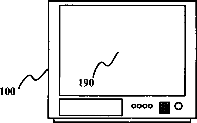
[0028] figure 1 A schematic diagram of a television is shown. As shown, the television 100 includes a display screen 190 . figure 2 A functional block diagram of television 100 is shown. As shown in the figure, the television set 100 includes an ambient light sampling device 110 , a main processor 120 , a display driving device 130 and a display screen 190 . Wherein, the ambient light sampling device 110 is used to sample the current ambient light intensity and obtain the current ambient light intensity value, and then the ambient light sampling device 1...


PUM


Abstract

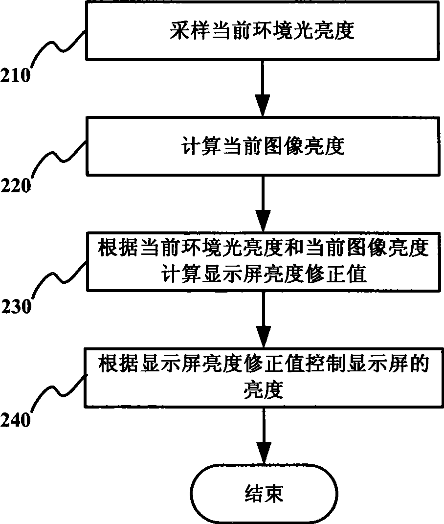
The invention provides a method for controlling display brightness, which comprises the following steps: obtaining the current environmental light brightness; calculating the current image brightness; calculating a correct value of the display brightness according to the current environmental light brightness and the current image brightness; controlling the display brightness according to the correct value of the display brightness. The invention fully considers the influence of the self image brightness on the virtual sense of a user and uses the self image brightness as a weighted factor to control the display brightness. The invention weights the environmental light brightness and the image brightness, controls the backlight of a display screen of a flat television by the weighted value of the environmental light brightness and the image brightness, and effectively solves the problem of flaring or unclear images when environmental light and the television images are both bright or dark.

Description

technical field [0001] The invention relates to a method for controlling the brightness of a display screen, in particular to a method for controlling the brightness of a display screen used in display devices such as televisions. Background technique [0002] With the improvement of living standards and the continuous development of video display technology, various video devices emerge in an endless stream, and their functions are also increasing. At the same time, users have higher and higher requirements for video devices. Taking TV as an example, the initial users only required the TV to be clear. However, with the continuous development of TV technology, especially the popularity of flat-panel TVs, people pay more and more attention to the display effect of TVs. However, in real life, when a user watches a TV program, the ambient light brightness around the TV often changes, and in such a changing environment, the display effect of the TV also changes accordingly. For...

Claims


Application Information

Patent Timeline
IPC IPC(8): G09G5/10G09G3/34G09G3/36
Inventor 周旭
Owner HISENSE VISUAL TECH CO LTD
Learn More