
LED packaging structure

A technology of LED packaging and LED brackets, which is applied in the direction of electrical components, circuits, semiconductor devices, etc., and can solve problems such as glare of lights

Pending Publication Date: 2018-02-09
崇辉半导体(深圳)有限公司
View PDF0 Cites 0 Cited by
  • Summary
  • Abstract
  • Description
  • Claims
  • Application Information

AI Technical Summary

Problems solved by technology

[0005] In this LED packaging structure, by setting a reflector above the chip, part of the light emitted from the chip is directed directly above and then reflected by the reflector to the side wall or bottom wall of the cavity and then reflected, which can prevent the light from going out directly, to a certain extent Solved the problem of glare on the light

Method used


Image

  • LED packaging structure
  • LED packaging structure
  • LED packaging structure

Examples


Embodiment Construction

[0019] In order to further explain the technical means and effects of the present invention to achieve the intended purpose of the invention, the specific implementation, structure, features and effects of the present invention will be described in detail below in conjunction with the accompanying drawings and examples.

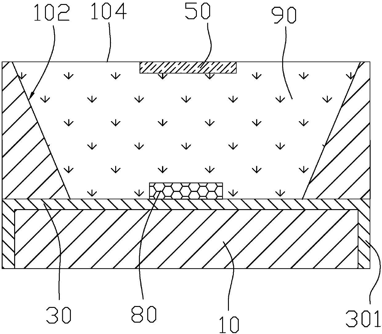
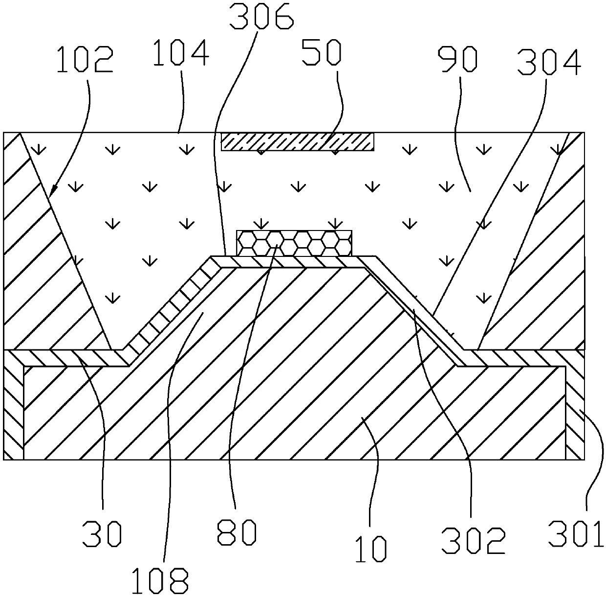
[0020] Such as figure 1 As shown, the LED packaging structure provided by the first embodiment includes an LED bracket and a chip 80 , and the LED bracket includes a bracket body 10 , a metal bracket 30 and a reflector 50 . A cavity 102 is opened on the top of the bracket main body 10 for accommodating the LED chip 80 . The metal bracket 30 extends into the cavity 102 of the bracket body 10 , and protrudes out of the bracket body 10 to form pins 301 . The reflector 50 is disposed above the chip 80 at a position corresponding to the chip 80 , and there is a space between the chip 80 and the chip 80 .

[0021] By setting the reflector 50 above the chip 80, pa...


PUM


Abstract

The invention provides an LED packaging structure. The structure comprises an LED support and a chip. The LED support comprises a support main body, a metal support and a reflection component. A top of the support main body is provided with a cavity so as to accommodate an LED chip. The metal support is inserted into the cavity of the support main body and is stretched out of the support main bodyso as to form a pin. The reflection component is arranged above the chip and is located at a position corresponding to the chip. And there is a gap between the reflection component and the chip. Themetal support comprises an embossment which is protruded towards the reflection component so as to form an inclined plane. In the LED packaging structure, through arranging the reflection component above the chip, a part of light emitted from the chip is emitted to a right above portion, then is reflected by the reflection component to a side wall or a bottom wall of the cavity, and then is reflected to the outside world so that the light can be prevented from being directly emitted to the outside world, and a problem of harsh light is solved to some extent.

Description

technical field [0001] The invention relates to the technical field of LEDs, in particular to an LED packaging structure. Background technique [0002] At present, LED devices have been increasingly widely used due to their advantages of low energy consumption, long life, fast response and high luminous efficiency, such as backlight of liquid crystal display devices and daily lighting. When LEDs are used for daily lighting, the light directly emitted by LED lamps is very dazzling. The way to prevent the glare of LED lights is generally: cover the LED lights with a frosted glass cover; wrap the LED lights with light-colored cloth; or cover the LED lights with a plastic shell. However, the above methods will affect the brightness of the LED lamp. Contents of the invention [0003] The purpose of the present invention is to provide a non-glare and high brightness LED packaging structure. [0004] The present invention provides an LED packaging structure, which includes an ...

Claims


Application Information

Patent Timeline
IPC IPC(8): H01L33/48H01L33/60
CPCH01L33/48H01L33/60
Inventor 郑建国罗小平
Owner 崇辉半导体(深圳)有限公司
Learn More