Adaptive transmission sensing drive assembly

A drive assembly and self-adaptive technology, applied in engine control, machine/engine, DC motor speed/torque control, etc., can solve problems such as mechanical efficiency loss, stop rotation, lack of road feeling, etc., to improve power performance, Reduced emissions, small size and light weight

Inactive Publication Date: 2009-03-11
SOUTHWEST UNIVERSITY
View PDF1 Cites 5 Cited by
  • Summary
  • Abstract
  • Description
  • Claims
  • Application Information

AI Technical Summary

Problems solved by technology

However, this sensing device is structurally designed to be installed on the wheel hub. Small motorcycles or electric bicycles are light in weight. If they are installed at the center of the rear wheel, the center of gravity will be tilted backward, which will affect the safe driving performance, and structurally quite complicated
[0004] Other transmission sensing devices that are operated and controlled by the rider only based on experience without knowing the driving resistance inevitably have the following problems: 1. When starting, going uphill and with a large load, due to the increase in driving resistance, the electric vehicle Speaking of it, it will force the motor speed to drop to work in the low-efficiency area, causing the motor to stall, heat up, or even stop rotating when the battery increases the supply current.
2. Since there is no driving torque-driving resistance sensor, it lacks "road sense" and cannot reflect the driving torque of the motor, the mechanical efficiency loss and motion resistance of the transmission system, and the change in the transmission inertia of the wheels and the rotating parts of the transmission system, so it is difficult to realize the driving force and driving force. Resistance Torque Balance Control
Can not solve the electric vehicle motor torque-speed characteristics, very incompatible with the driving requirements of the vehicle, often contrary to it, and difficult to achieve scientific problems of precise control
3. The installation space at the driving wheel is small, and it is difficult to accommodate the automatic transmission and other new technologies after the motor is installed;

Method used


Image

  • Adaptive transmission sensing drive assembly
  • Adaptive transmission sensing drive assembly
  • Adaptive transmission sensing drive assembly

Examples


Embodiment Construction

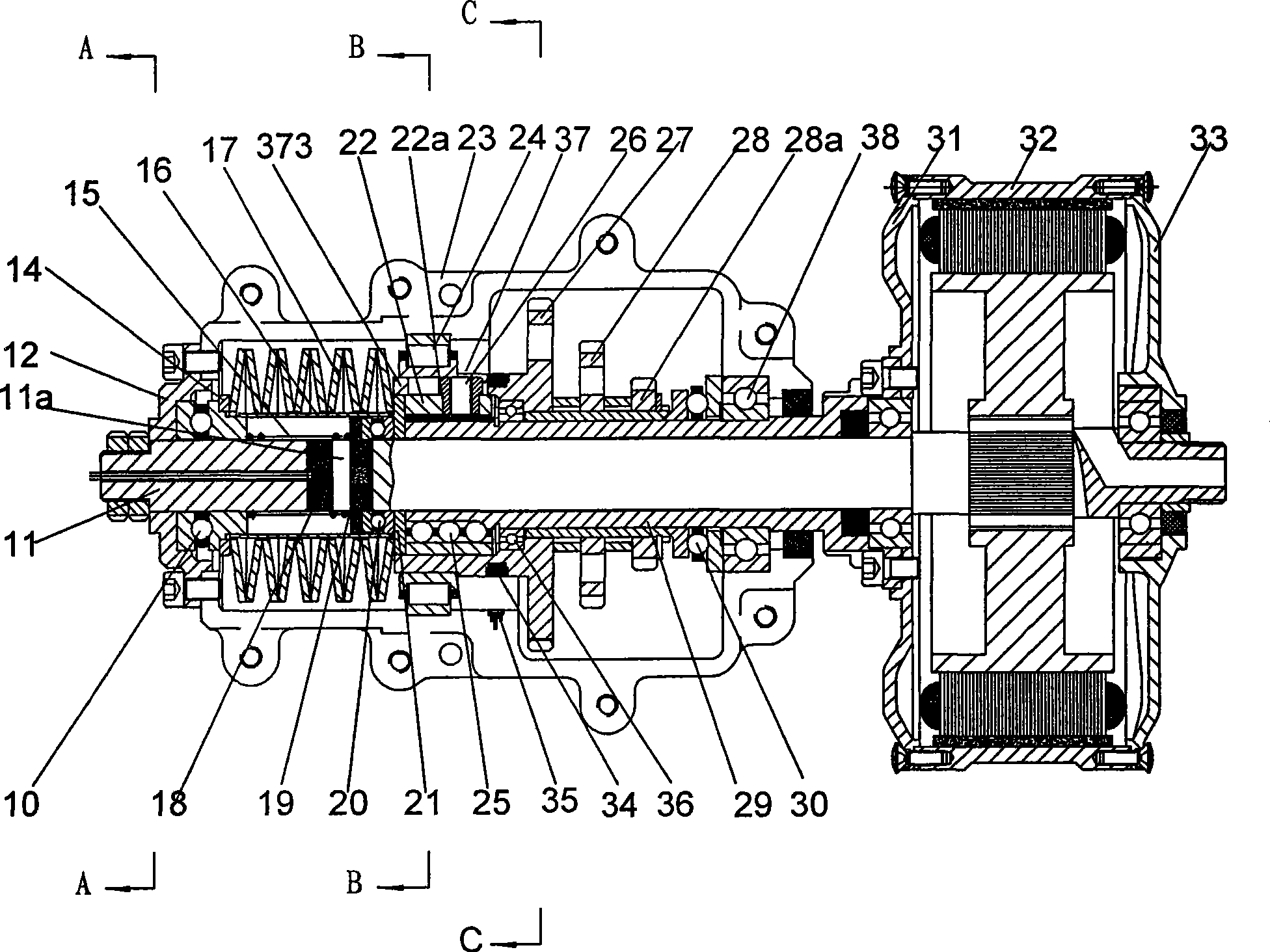
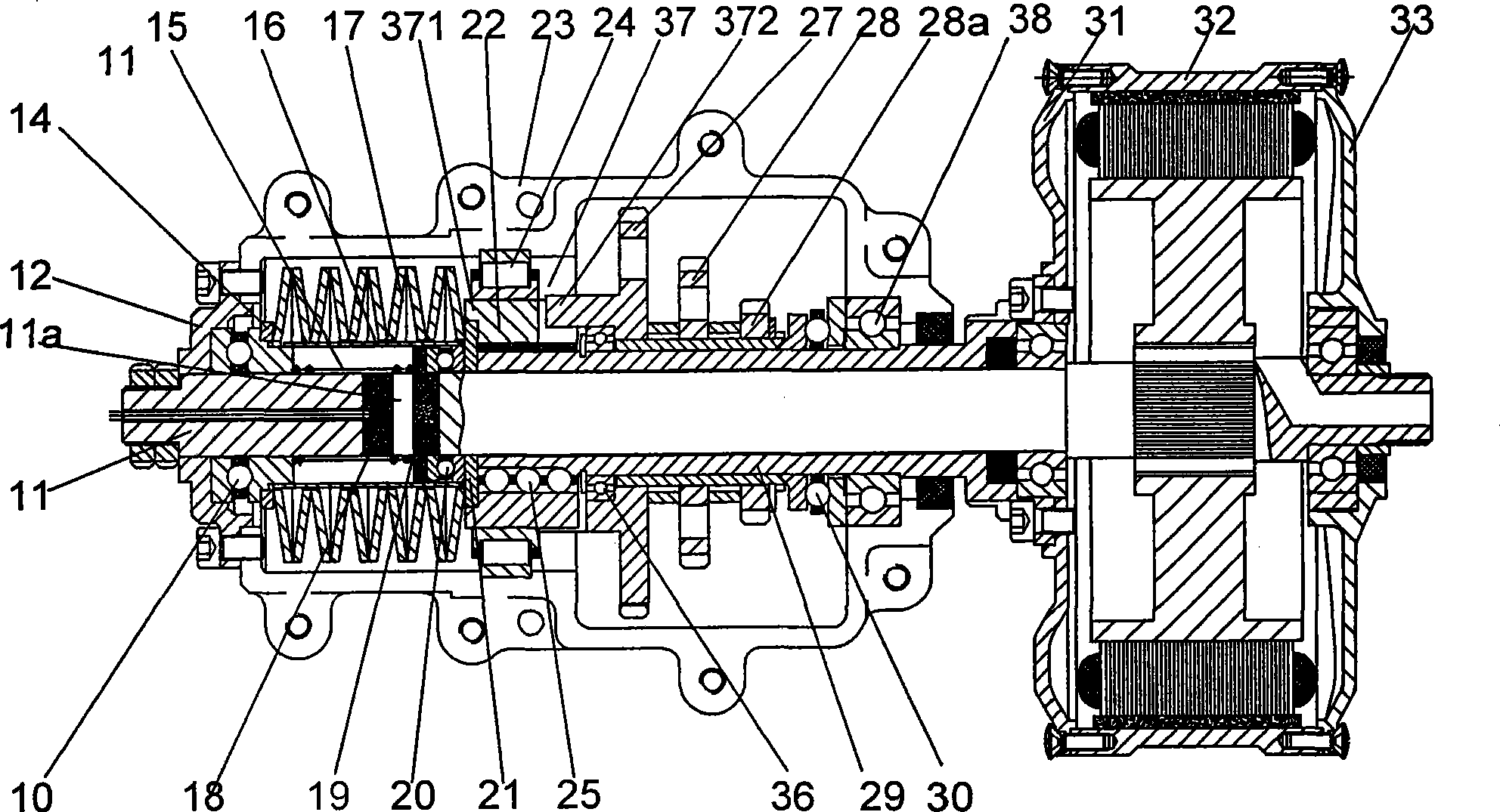
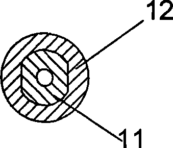
[0032] figure 1It is a schematic structural view of the present invention, as shown in the figure: the power equipment of the present embodiment is a motor, and the direction of rotation of the motor is counterclockwise as viewed from right to left. The motor is arranged outside the box body, the fixed shaft 11 is set inside the box body 23, the part of the right end protruding from the box body 23 is rigidly connected with the motor stator, the left end and the left end cover 12 of the box body 23 are processed into a flat square shaft, and the corresponding left end The cover 12 cooperates with it to form a flat square hole to form a mesh, and is fixed on the box body through the left end cover 12 of the box body. The transmission sleeve 29 is rotatably matched with the fixed shaft 11 through the first radial bearing 38. The left end cover 31 and the right end cover 33 of the motor It is rigidly connected with the motor rotor housing 32 by screws, the right end cover 33 and ...


PUM


Abstract

The invention discloses an adaptive transmission sensing drive assembly which comprises a case; a fixed axle is fixedly arranged inside the case, a driving sleeve is sheathed on the fixed axle in a rotatable way, a sensing cam seat, and the driving sleeve and a sensing rolling body form a radial meshing and axial moveable mechanism; the driving sleeve, the sensing cam seat, a sensing cam pin, a sensing torus axial cam and an active quick block gear form a power transmission mechanism; a sensing spring, an Hall sensor, a sensing element and a return spring form a sensing mechanism; the Hall sensor and the sensing element are fixed on the fixed axle, and a displacement thrust ring is arranged between the power transmission mechanism and the sensing mechanism; the sensor of the invention is directly accessed into a transmission mechanism, thus precisely detecting a resistance signal of the torque, providing reliable foundation for a controller to carry out exact adjustment, and causing locomotives to improve efficiency, reduce discharge, and improve dynamic property, economical efficiency, safety and comfort.

Description

technical field [0001] The invention relates to a motor vehicle drive assembly, in particular to an adaptive transmission sensor drive assembly. Background technique [0002] In the prior art, electric vehicles, motorcycles, and electric bicycles basically directly control the current or the throttle to control the speed through the speed control handle or the accelerator pedal, or use the manual mechanical automatic transmission mechanism to realize the speed change. The operation of the handle or accelerator pedal depends entirely on the driver's operation, which often results in a mismatch between the operation and the driving conditions, resulting in unstable operation of the engine or motor, and stalling. [0003] Motor vehicles need to achieve intelligent control of current or throttle, and load or torque are important parameters. The measurement of this index generally uses a variety of sensors to obtain relevant parameters respectively, and then make judgments. For...

Claims


Application Information

Patent Timeline
IPC IPC(8): G01L5/13F02D29/02H02P7/00
Inventor 薛荣生林毓培郝允志
Owner SOUTHWEST UNIVERSITY
Why Eureka
Try Eureka