V-belt type continuously variable transmission

A continuously variable transmission and pulley technology, which is applied to components with teeth, belts/chains/gears, mechanical equipment, etc., can solve the problem of longer distance between the electric motor and the axially moving threaded parts, and achieve noise suppression, The effect of shortening the distance between shafts and smooth axial sliding

Inactive Publication Date: 2011-05-25
HONDA MOTOR CO LTD
View PDF1 Cites 0 Cited by
  • Summary
  • Abstract
  • Description
  • Claims
  • Application Information

AI Technical Summary

Problems solved by technology

In the conventional technology, in order not to interfere with the flange of the axially moving screw member of the pulley control part reduction gear mechanism and the pulley movable half drive mechanism, they are arranged so that they do not overlap when viewed from the side. Therefore, the distance from the electric motor to the axially moving screw member becomes longer, and the pulley movable half drive mechanism becomes larger (for example, refer to Patent Document 1)

Method used


Image

  • V-belt type continuously variable transmission
  • V-belt type continuously variable transmission
  • V-belt type continuously variable transmission

Examples


Embodiment Construction

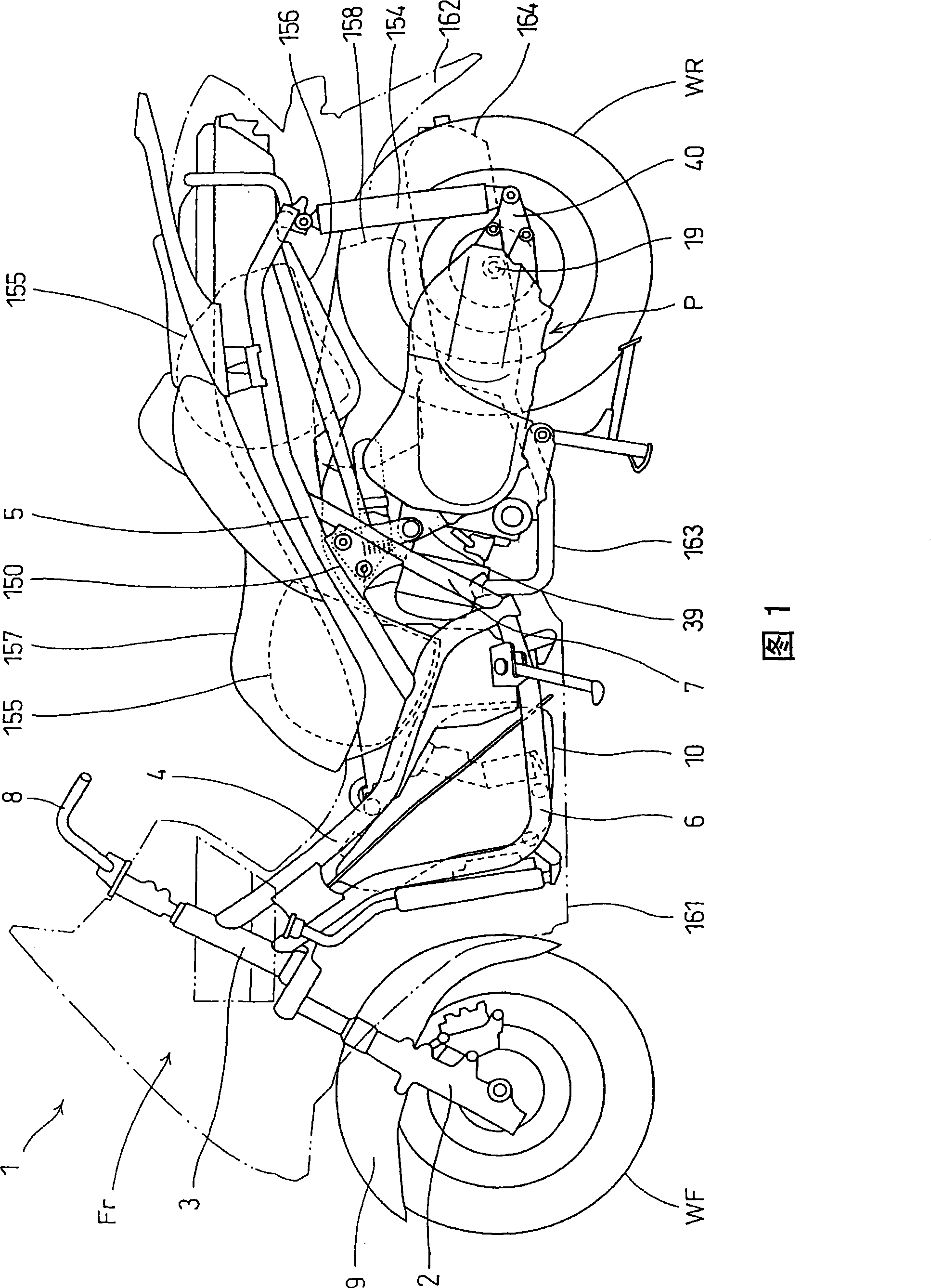
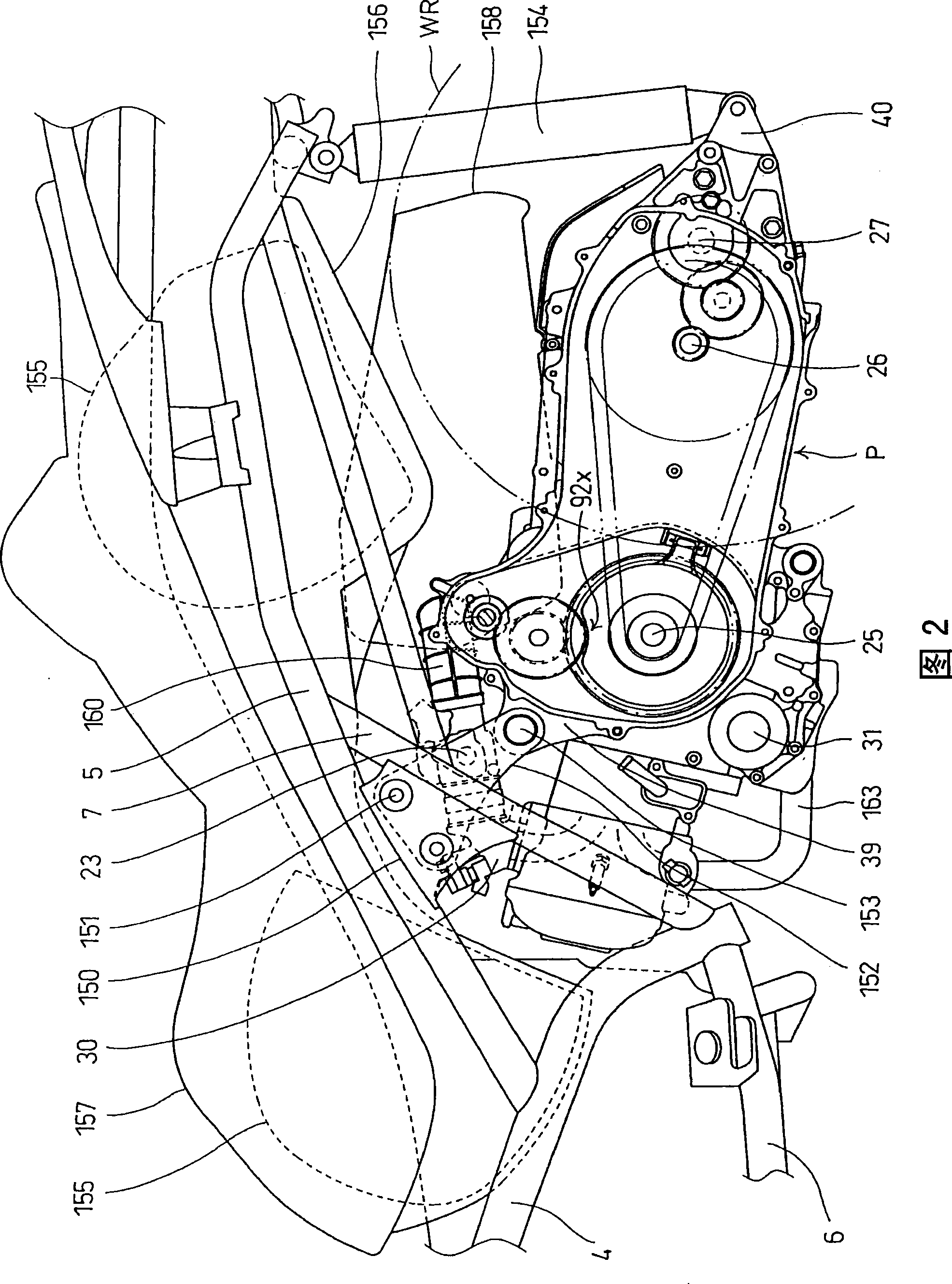
[0028] figure 1 It is a side view of a motorcycle 1 equipped with a power unit P according to an embodiment of the present invention, figure 2 It is an enlarged view of the rear portion of the above-mentioned motorcycle 1 . exist figure 1 Among them, the body frame Fr of the motorcycle 1 includes: a head pipe 3 that rotatably supports the front fork 2; a main frame 4 extending rearward and downward from the head pipe 3; A pair of left and right rear frames 5 extending from the upper rear; a lower frame 6 extending downward from the head pipe 3 and bent rearward, and connected to the lower end of the main frame 4; middle frame7. The front wheel WF is pivotally supported on the lower end of the front fork 2 , the steering wheel 8 is steered in the connection direction of the upper part of the front fork 2 , and the front fender 9 covering the upper side of the front wheel is supported on the front fork 2 . A fuel tank 10 is provided between the main frame 4 and the lower ...


PUM


Abstract

To provide a structure in a V-belt type continuously variable transmission including: a pulley fixed half fixed onto and supported by a rotational shaft, a pulley movable half supported on the rotational shaft to be movable in the axial direction, a belt held by and between the pulley fixed half and the pulley movable half; and a screw-type feeding mechanism including a constant-position rotatingthreaded member and a threaded member for axial-direction movement. The constant-position rotating threaded member is supported on the rotational shaft so as to be unmovable in the axial direction, and is driven to rotate by an electric motor via a reduction gear mechanism. The threaded member for axial-direction movement is held by the pulley movable half so as to be movable in the axial direction of the rotational shaft and is fitted to the constant-position rotating threaded member so as not to rotate about the rotational shaft. The structure provided by the present invention enables the shortening of a distance between an electric motor and the threaded member for axial-direction movement and size reduction in the V-belt type continuously variable transmission. A rotation stopper is formed in a flange portion of the threaded member for axial-direction movement to restrict the rotation of the threaded member for axial-direction movement. In addition, the flange portion is provided with a cutaway formed along the contour of the leading edges of teeth of a reduction gear.

Description

technical field [0001] The present invention relates to a V-belt type continuously variable transmission that realizes the miniaturization of the pulley movable semi-body driving mechanism. Background technique [0002] In a V-belt type continuously variable transmission that uses an electric motor to change the gear ratio, in order to configure the power unit compactly, it is required to properly arrange the electric motor, the reduction gear mechanism of the pulley control unit, the position sensor of the movable half of the pulley, and the like. In the conventional technology, in order not to interfere with the flange of the axially moving threaded member of the reduction gear mechanism of the pulley control part and the pulley movable half body drive mechanism, they are arranged so that they do not overlap when viewed from the side. Therefore, the distance from the electric motor to the axially moving screw member becomes longer, and the pulley movable half drive mechani...

Claims


Application Information

Patent Timeline
Patent Type & Authority Patents(China)
IPC IPC(8): F16H59/68F16H61/02F16H9/18
CPCF16H9/18F16H63/062F16H55/56
Inventor 石川秀男森田豪池田直机
Owner HONDA MOTOR CO LTD
Why Eureka
Try Eureka