Mounting structure of start motor

A starter motor and driving force technology, which is applied to the starting of the engine, the starting device with a mechanical power storage, the starting of the electric motor for the engine, etc., and can solve the problems of large-scale equipment, complicated and enlarged structure of the power transmission mechanism, etc.

Inactive Publication Date: 2006-07-26
HONDA MOTOR CO LTD
View PDF1 Cites 0 Cited by
  • Summary
  • Abstract
  • Description
  • Claims
  • Application Information

AI Technical Summary

Problems solved by technology

[0008] However, the gear transmission of the above-mentioned rotational driving force via the above-mentioned plurality of intermediate shafts not only leads to a complicated structure of the power transmission mechanism, but also increases the number of components such as gears, resulting in an increase in the size of the equipment, thereby reducing the transmission efficiency of the above-mentioned rotational driving force. losses also increased

Method used


Image

  • Mounting structure of start motor
  • Mounting structure of start motor
  • Mounting structure of start motor

Examples


Embodiment Construction

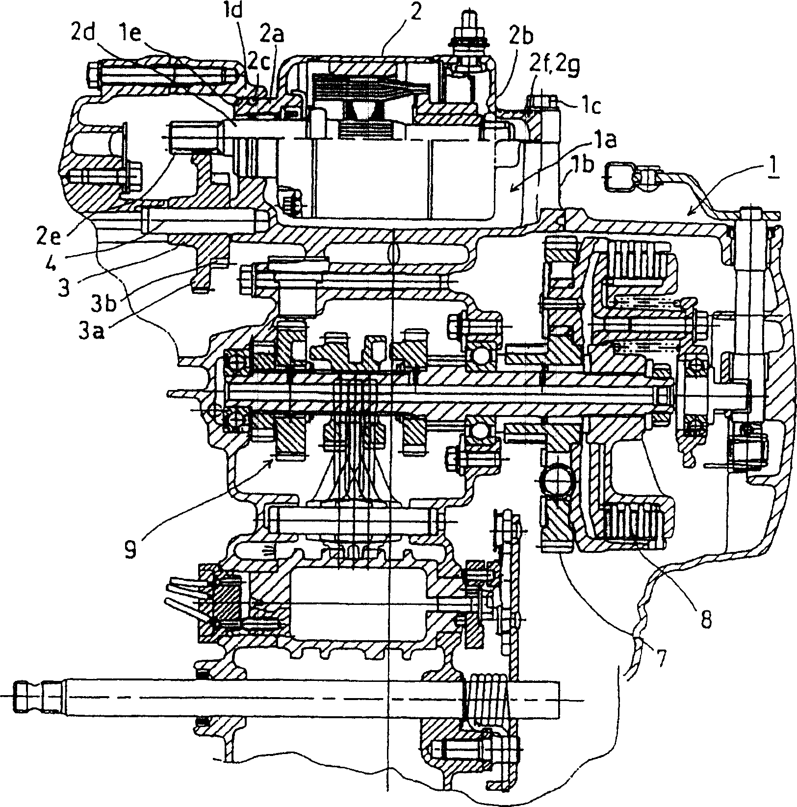
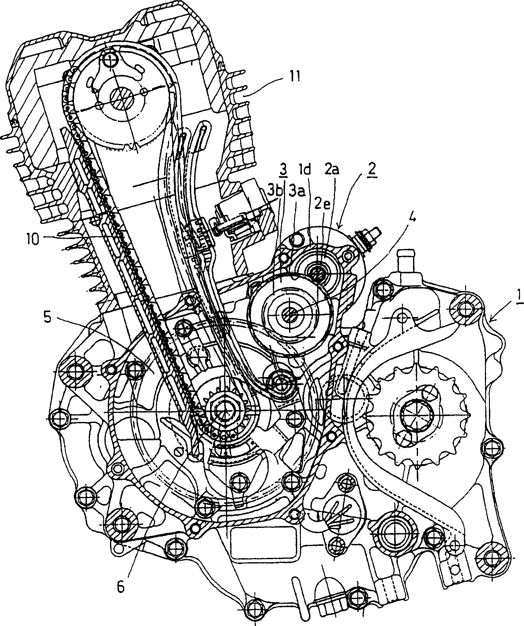
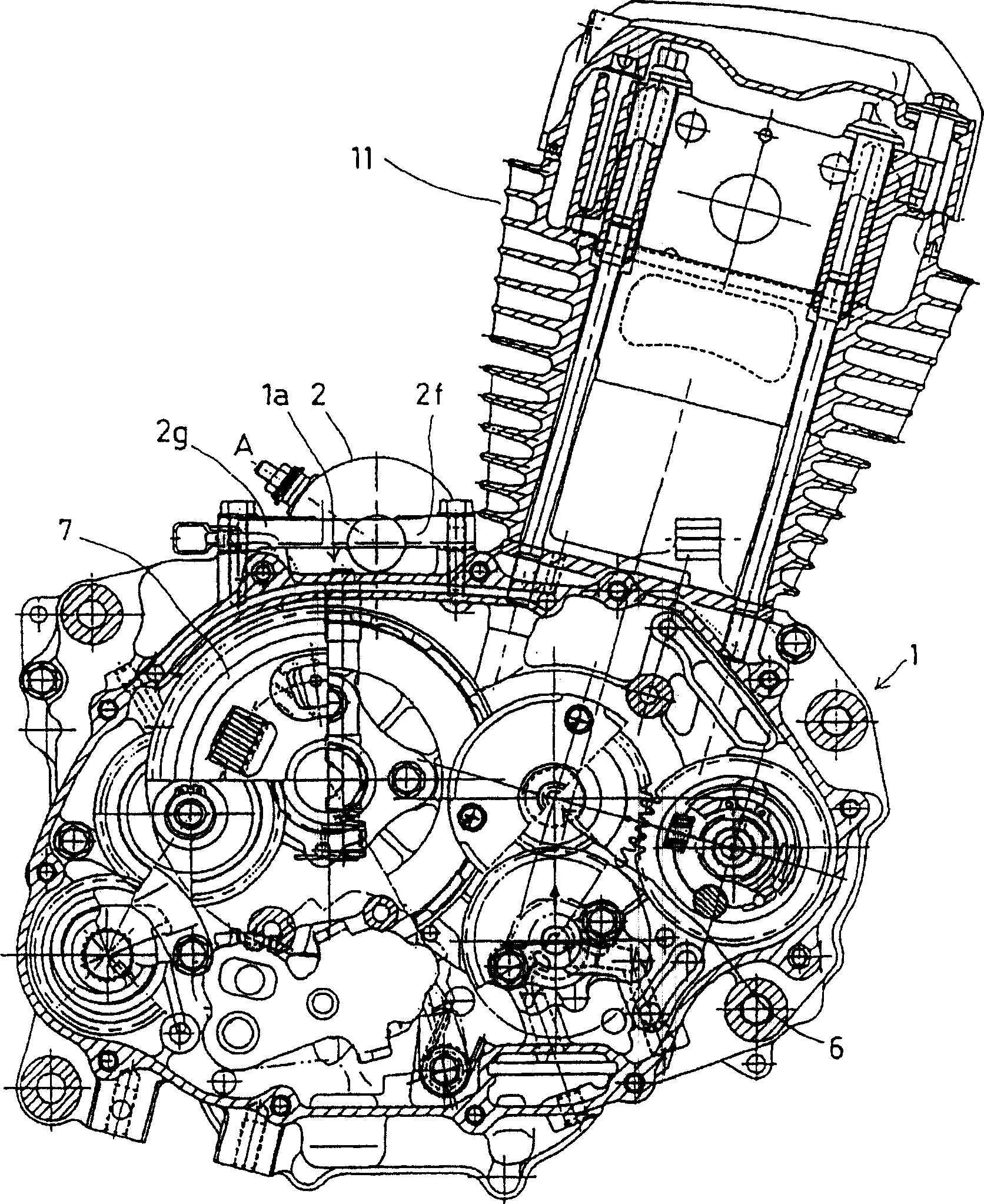
[0022] Below, according to Figure 1 to Figure 4 Embodiments of the present invention will be described.

[0023] figure 1 Represents a longitudinal sectional view in the direction of a crankshaft (not shown) of a crankcase 1 in an internal combustion engine, in which figure 1 In the figure, the partial structure of the crankcase 1 is shown, and in this figure, the starter motor 2 and its surrounding structural parts which are the characteristic structural part of this invention are described.

[0024] Also, an intermediate gear 3 and the like meshed with a gear 2e integral with the rotating shaft 2d of the above-mentioned starter motor 2 are shown, and the intermediate gear 3 is connected to the figure 1 The driven gear 5 on the side of the crankshaft 6 not shown is meshed, and the rotational driving force of the above-mentioned starter motor 2 is transmitted to the above-mentioned crankshaft 6 via the above-mentioned intermediate gear 3 (refer to figure 2 ).

[0025]...


PUM


Abstract

To simplify a rotational force transmission mechanism by reducing the distance between a rotary shaft of a starter motor and a crankshaft to decrease the number of intermediate shafts for the transmission of rotation driving force from the rotary shaft of the starter motor to the crankshaft. A recess 1a is formed in the upper part of a crankcase 1, and the starter motor 2 is placed in the recess 1a, thereby reducing the distance between the rotary shaft 2d of the starter motor 2 and the crankshaft. The transmission of rotation driving force from a gear of the rotary shaft 2d of the starter motor 2 to the crankshaft through an intermediate gear is achieved by one intermediate shaft 4 only, thereby simplifying the structure of the mechanism for the rotational force transmission.

Description

technical field [0001] The present invention relates to a mounting structure of a starter motor in an internal combustion engine, and more particularly to the above-mentioned internal combustion engine configured so that the arrangement positions of the starter motor and the crankshaft are close to each other, and the distance between the rotation shaft of the starter motor and the crankshaft is shortened. Starter motor installation structure. Background technique [0002] The starter motor in the conventional internal combustion engine is installed relative to the outline drawn by the crank case shell of the internal combustion engine, and is installed according to the relationship outside the outline, and the starter motor is arranged at a position far from the crankshaft. On the other hand, the distance between the rotation shaft of the starter motor and the two shafts of the above-mentioned crankshaft increases, and the transmission of the rotational driving force from t...

Claims


Application Information

Patent Timeline
Patent Type & Authority Patents(China)
IPC IPC(8): F02N15/02F02B67/00F02B67/04F02F7/00F02N11/00
CPCF02F7/0043F02N15/006F02N15/02
Inventor 神户敬司佐藤智康
Owner HONDA MOTOR CO LTD
Why Eureka
Try Eureka