
I-shaped electric-controlled beam scanning antenna housing constructed by microwave diode

A beam scanning and I-shape technology, applied in the field of radome, can solve the problems of complicated production process and so on

Inactive Publication Date: 2009-03-04
ZHEJIANG UNIV
View PDF0 Cites 14 Cited by
  • Summary
  • Abstract
  • Description
  • Claims
  • Application Information

AI Technical Summary

Problems solved by technology

However, when microwave diodes are added, many through holes need to be drilled on the heterogeneous dielectric material board, and only manual soldering can be performed, and the manufacturing process is complicated.

Method used


Image

  • I-shaped electric-controlled beam scanning antenna housing constructed by microwave diode
  • I-shaped electric-controlled beam scanning antenna housing constructed by microwave diode
  • I-shaped electric-controlled beam scanning antenna housing constructed by microwave diode

Examples


Embodiment Construction

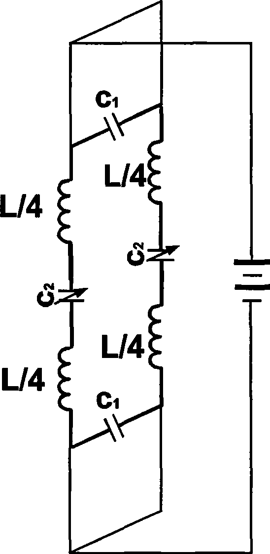
[0017] Such as figure 1 As shown, in order to manufacture this kind of radome that is convenient for voltage to control the scanning direction, a new material of double-sided I-shaped electrically controlled anisotropic medium based on the theory of anisotropic medium is used, and microwave diodes are added to the material. Where k is the incident direction of the beam, E is the polarization direction of the electric field, and H is the polarization direction of the magnetic field.

[0018] Such as figure 1 , image 3 As shown, the present invention prints I-shaped copper wires with the unit structure on the front and back of the FR4 dielectric board, and prints n and m unit lengths respectively in the horizontal and vertical directions of the dielectric board to form n×m double-sided uniformly distributed I-shaped structures. Symmetrical anisotropic dielectric plate; microwave diodes are added to the I-shaped structure of each unit, and a DC voltage is applied to each unit ...


PUM


Abstract

The invention discloses an H-shaped electric control beam scanning radome which is formed by using a microwave diode; a copper wire with H-shaped unit structure is painted on the front surface and the back surface of an FR4 dielectric slab and the dielectric slab is painted with n and m unit length respectively horizontally and longitudinally so as to form the double surface symmetrical heterodromous dielectric slab with the number of n multiplied by m, the same H-shaped structure and uniform distribution; the microwave diode is added in the H-shaped structure of each unit, direct current voltage is externally added to each unit of the first line of the upper end of the heterodromous dielectric slab so as to lead the microwave diode in each row of units to have the same direct current bias and all the units in each row are parallel; and the difference of two adjacent rows of added direct current voltage is adjusted to lead the beam running through the two adjacent rows to have the same phase difference so as to realize beam deflection. The capacitance of the diode is controlled by the direct current voltage so as to change the resonance frequency heterodromous medium and achieve the purpose of electric control adjustment of the scanning direction. The invention has simple electric control circuit, good electric control adjustability, uniform structure, small size, light weight, simple manufacture and low cost.

Description

technical field [0001] The invention relates to a radome for antenna direction scanning, in particular to an I-shaped electronic control beam scanning radome constructed by microwave diodes. Background technique [0002] In order to allow the outgoing beam of the antenna to scan as expected, a beam electronic scanning antenna came into being. The common electronic beam scanning technology is based on the phased array technology, and the overall beam scanning of the antenna is realized by controlling the relative phase change of each radiation source in the array antenna. This technology has the advantage of fast scanning speed. However, because the phased array technology requires relatively complex electronic control circuits and a large number of phase shifting devices, its cost has remained high. The phase shifters of common electronically controlled scanning antennas are all realized by materials such as ferrite and semiconductor, and the use of these materials restric...

Claims


Application Information

Patent Timeline
Patent Type & Authority Applications(China)
IPC IPC(8): H01Q3/34H01Q1/42
Inventor 王志宇王东兴姜涛彭亮皇甫江涛冉立新
Owner ZHEJIANG UNIV
Learn More