Lens system

A lens system and lens technology, applied in optical components, optics, instruments, etc., to achieve good image quality, miniaturization, and small length

Inactive Publication Date: 2010-06-02
HONG FU JIN PRECISION IND (SHENZHEN) CO LTD +1
View PDF6 Cites 0 Cited by
  • Summary
  • Abstract
  • Description
  • Claims
  • Application Information

AI Technical Summary

Problems solved by technology

And this increased demand itself requires further miniaturization of the lens system.

Method used


Image

  • Lens system
  • Lens system
  • Lens system

Examples


Embodiment 1

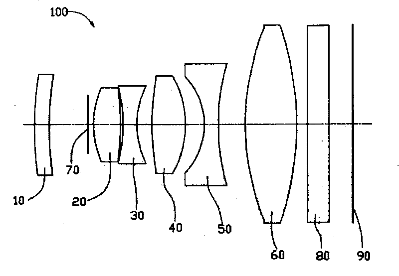
[0037] Each optical element of the lens system 100 meets the conditions of Table 1, and its TT=11.64 millimeters (mm); f=6.91mm; f 23 =19.2939mm; FNo=3.19; 2ω=56°.

[0038] Table 1

[0039] lens system 100

[0040] lens system 100

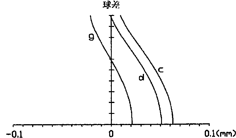
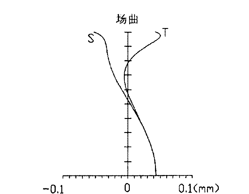
[0041] In the lens system 100 of the first embodiment, the spherical aberration, field curvature and distortion are respectively as follows Figure 2 to Figure 4 shown. figure 2 Among them, the spherical aberration values ​​observed for g-line (wavelength value 435.8 nanometers (nm)), d-line (wavelength value 587.6nm), and c-line (wavelength value 656.3nm) respectively. Generally speaking, the spherical aberration value generated by the lens system 100 of Embodiment 1 for visible light (with a wavelength range between 400nm and 700nm) is within the range of (-0.1mm, 0.1mm), image 3 The S (meridian field curvature value) and T (sagittal field curvature value) are both controlled within the range of (-0.1mm, 0.1mm). Figure ...

Embodiment 2

[0043] Each optical element of the lens system 100 satisfies the conditions of Table 2, and its f=7.098mm; f 23 =18.8125mm; FNo=3.19; 2ω=53.38°.

[0044] Table 2

[0045] lens system 100

Radius of curvature (mm)

Thickness (mm)

Refractive index

Abbe number

subject

gigantic

1000

---

---

The surface of the first lens 10 on the object side

138

0.515

1.48749

70.4058

The image-side surface of the first lens 10

38.5071

1.2933

---

---

Aperture 70

gigantic

0.2166

---

---

The surface of the second lens 20 on the object side

3.434642

0.9954933

1.90217

40.7651

The surface of the second lens 20 on the image side

-12.82318

0.1

---

---

The surface of the third lens 30 on the object side

-6.115171

0.515

1.729672

28.6914

The surface of the third lens 30 on the image side

3....


PUM


Abstract

The invention relates to a lens system which sequentially comprises a first lens with negative power, a second lens with positive power, a third lens with negative power, a fourth lens with positive power, a fifth lens with negative power and a sixth lens with positive power from the object side to the image side. The lens system satisfies the following conditions: TT / f is less than or equal to 168 and f / f23 is more than 0.3 and less than 0.4; wherein, TT is the distance from the surface of the first lens near the object side to the image side of the system, f23 is the effective focal length of the lens combination of the second lens and the third lens, and f is the effective focal length of the lens system.

Description

technical field [0001] The invention relates to a lens system, in particular to a lens system for electronic equipment. Background technique [0002] In recent years, with the development of multimedia, there is an increasing demand for imaging elements of solid-state imaging devices such as CCD (Charged Coupled Device) or CMOS (Complementary Metal Oxide Semiconductor) used in laptop computers, videophones, and mobile phones. And this increased demand itself requires further miniaturization of the lens system. [0003] On the other hand, due to the improvement of the process technology of these solid-state imaging devices such as CCD or CMOS, imaging devices with each pixel only a few microns in size have been produced, which makes the system miniaturized and improves the resolution requirements of the camera lens. Therefore, providing a lens system with a small length, excellent optical performance and good imaging quality is the development direction of today's miniature ...

Claims


Application Information

Patent Timeline
Patent Type & Authority Patents(China)
IPC IPC(8): G02B13/00G02B9/62G02B1/02
CPCG02B13/005G02B13/22G02B9/62
Inventor 林群翎黄俊翔李崇
Owner HONG FU JIN PRECISION IND (SHENZHEN) CO LTD
Why Eureka
Try Eureka