
Feeding machine with rolling wheel

A feeder and roller technology, applied in metal processing equipment, feeding devices, manufacturing tools, etc., can solve problems such as single function, uncoordinated action coordination, and economic loss of enterprises, and achieve low failure rate, accurate relaxation point, good stability effect

Inactive Publication Date: 2009-03-04
常州市佳王精密机械有限公司
View PDF0 Cites 25 Cited by
  • Summary
  • Abstract
  • Description
  • Claims
  • Application Information

AI Technical Summary

Problems solved by technology

[0002] Punch is a commonly used stamping production equipment. In the past, manual feeding was usually used to feed materials, resulting in a high accident rate in production safety. Therefore, people designed and manufactured various feeding machines to replace manual feeding to punches. This increases the safety of production
The materials used for punching machines generally need to be flat plates, and the coiled materials need to be leveled to eliminate internal stress before they can be used. After leveling, the plates are sent to the punching machine through the feeding machine for punching processing. However, the existing feeding machines have more complicated structures and more functions. Single, and the matching performance with the punching machine is poor, especially in the conversion between the clamping and feeding of the plate, the mechanical control method is usually used, that is, the use of the lever method to mechanically control the feeder to the plate through the movement of the punching machine. Clamping and release, which often lead to uncoordinated and out-of-place situations, and in severe cases, production accidents and economic losses to the enterprise

Method used


Image

  • Feeding machine with rolling wheel
  • Feeding machine with rolling wheel
  • Feeding machine with rolling wheel

Examples


Embodiment Construction

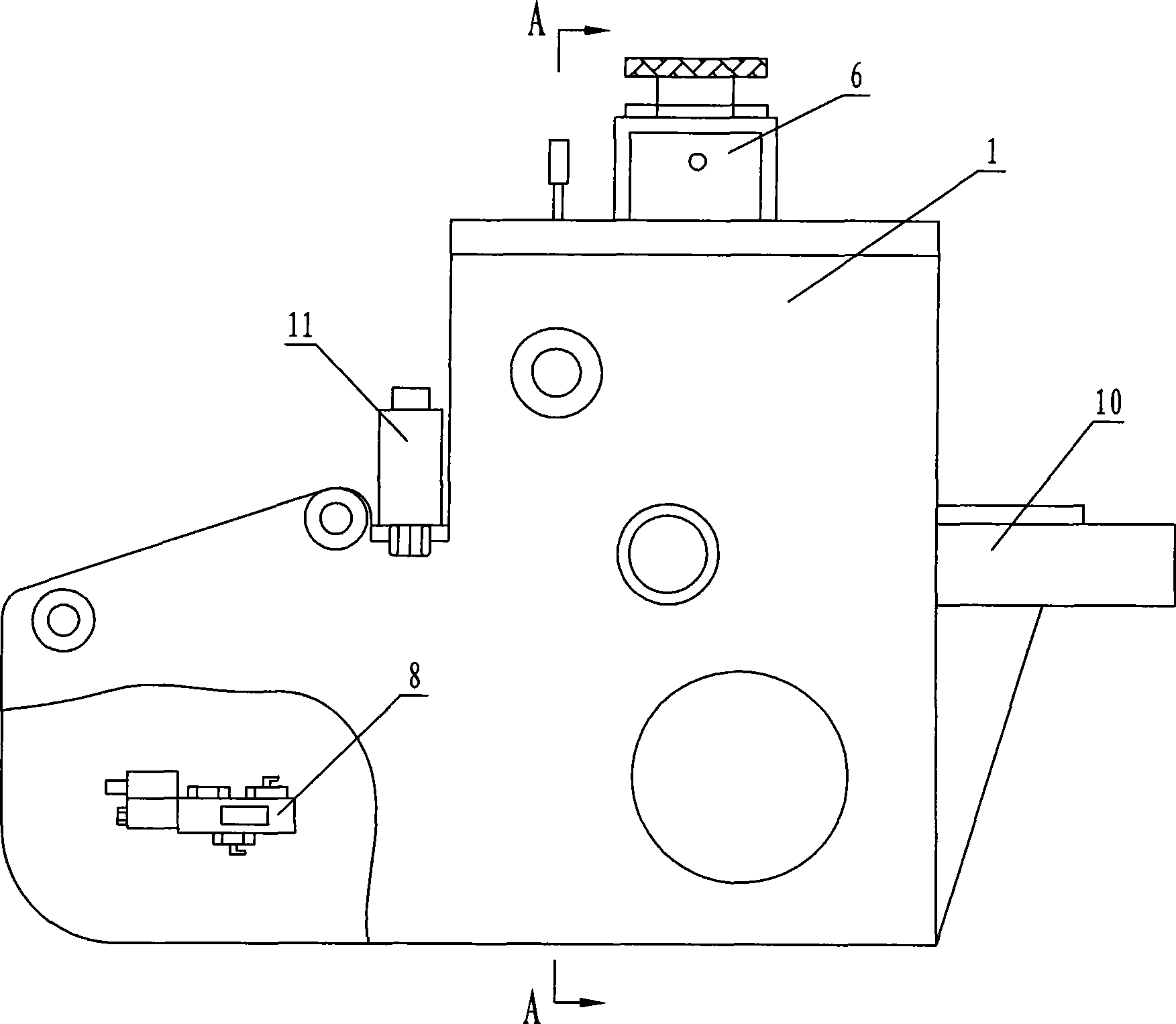
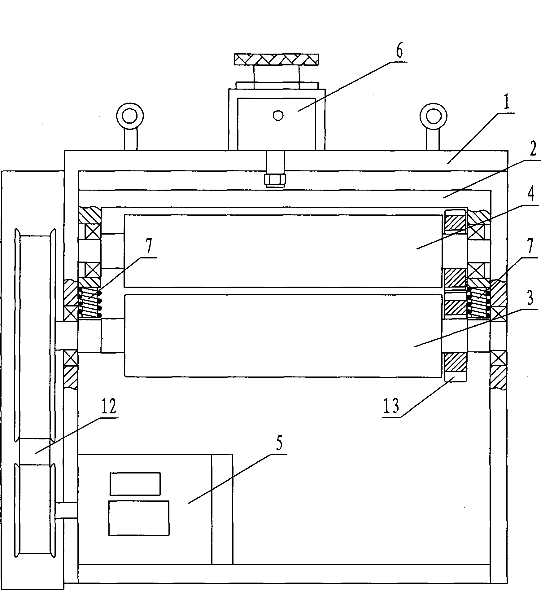
[0013] Such as figure 1 figure 2 image 3 A kind of roller feeding machine shown has a frame 1, and an upper roller seat 2 is movably arranged in the frame 1, an upper roller 4 is fixed on the upper roller seat 2, and a lower roller 3 is fixed on the frame 1, and the machine A servo motor 5 is provided at the lower part of the frame 1, which starts when feeding and stops when not feeding. The servo motor 5 drives the lower roller 3 to rotate through the synchronous belt 12, and the lower roller 3 and the upper roller 4 are connected through a gear 13 transmission. A cylinder 6 is provided at the top of the frame 1. The piston rod of the cylinder 6 passes through the upper plane of the frame 1 and is fixedly connected with the upper roller seat 2. A spring 7 is connected to the lower part of both ends of the upper roller seat 2. Through the action of the spring 7, it can drive The upper roller 4 arranged on the upper roller seat 2 moves to the lower roller 3 and clamps the p...


PUM


Abstract

The invention discloses a feeder with rollers, which is provided with a frame. An upper roller seat is moveably arranged in the frame; an upper roller is fixed on the upper roller seat; a lower roller is arranged on the frame; a servo motor is arranged at the lower part of the frame and in transmission connection with the lower roller; the lower roller is in transmission connection with the upper roller; a cylinder and an electromagnetic reversing valve are arranged on the frame; a piston rod of the cylinder passes through the upper plane of the frame to fixedly connect the upper roller seat; the electromagnetic reversing valve is connected with a pipeline of the cylinder; a spring is connected to the upper roller seat, and the upper roller arranged on the upper roller seat is driven under the action of the spring to move towards the lower roller and clamp board material tightly. The invention adopts the servo motor and a structure of the spring clamping feed and the cylinder loosening, feeding and loosening signals are sent to the feeder by the punch, and the movement of the cylinder is controlled through the electromagnetic reversing valve, so as to realize the feeding during clamping and no feeding during loosening. Therefore, the feeder and the punch can be harmoniously matched with good stability and wide applicability.

Description

technical field [0001] The invention relates to the technical field of plate feeders, in particular to a roller feeder that can be produced in cooperation with a punching machine. Background technique [0002] Punch is a commonly used stamping production equipment. In the past, manual feeding was usually used to feed materials, resulting in a high accident rate in production safety. Therefore, people designed and manufactured various feeding machines to replace manual feeding to punches. This increases the safety of production. The materials used for punching machines generally need to be flat plates, and the coiled materials need to be leveled to eliminate internal stress before they can be used. After leveling, the plates are sent to the punching machine through the feeding machine for punching processing. However, the existing feeding machines have more complicated structures and more functions. Single, and the matching performance with the punching machine is poor, espe...

Claims


Application Information

Patent Timeline
Patent Type & Authority Applications(China)
IPC IPC(8): B21D43/09B21D43/00
Inventor 唐奇南肖检发
Owner 常州市佳王精密机械有限公司
Learn More