Engine gas fuel supply apparatus

A gas fuel and supply device technology, applied to fuel injection devices, oil supply devices, engine components, etc., can solve problems such as valve core movement obstacles, and achieve the effects of preventing poor operation, efficient heating, and cost reduction

Inactive Publication Date: 2009-02-25
KEIHIN CORP
View PDF1 Cites 4 Cited by
  • Summary
  • Abstract
  • Description
  • Claims
  • Application Information

AI Technical Summary

Problems solved by technology

However, even if the evaporator is used to heat the fuel, as long as the gas fuel injection valve has not become high temperature, the adhered oil in the gas fuel injection valve will be placed in a state of low temperature and high viscosity, so the action of the valve core will be affected. bring obstacles

Method used


Image

  • Engine gas fuel supply apparatus
  • Engine gas fuel supply apparatus
  • Engine gas fuel supply apparatus

Examples


Embodiment 1

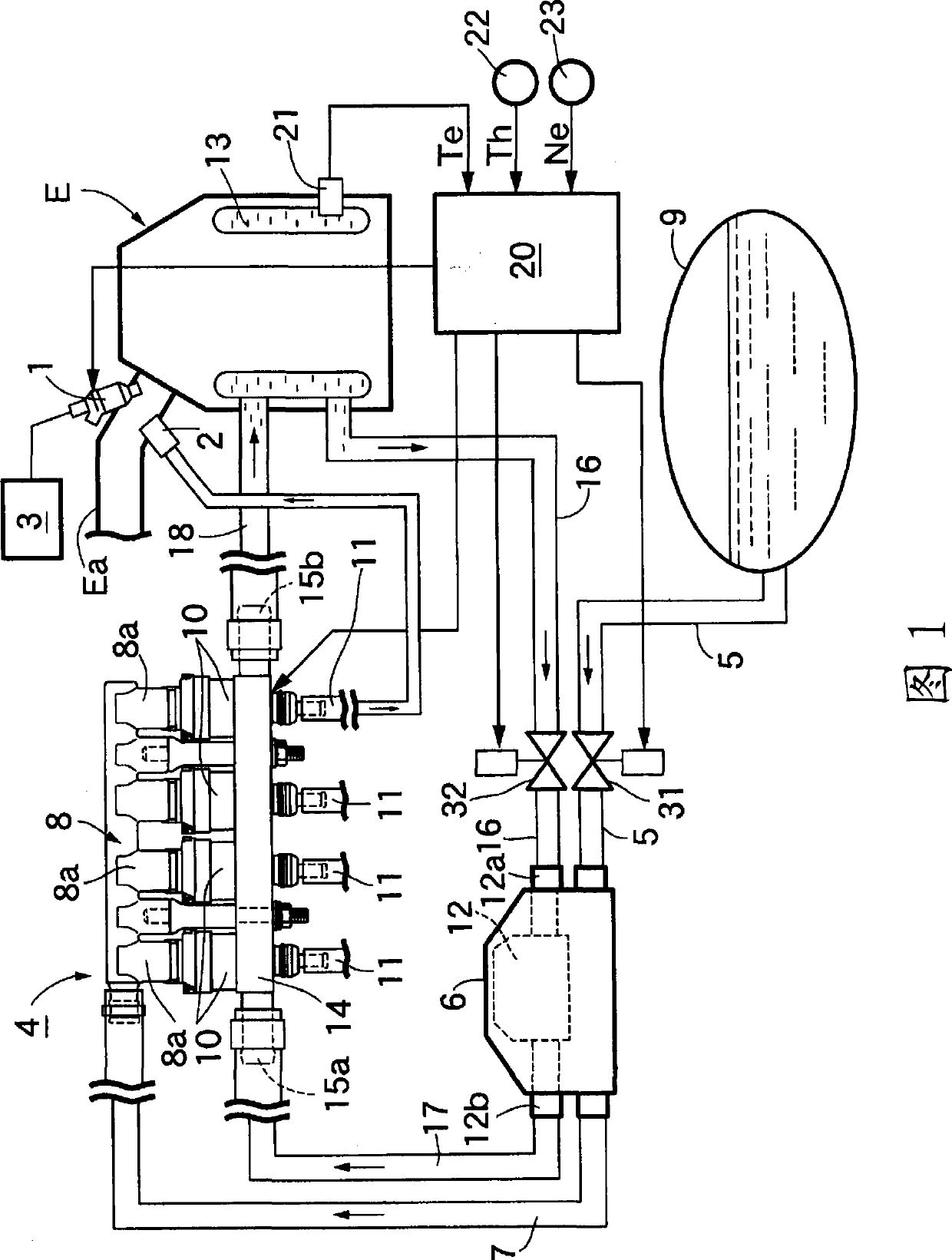
[0039] First of all, in Fig. 1, on the side of the cylinder head of the multi-cylinder engine E are installed: gasoline fuel injection valves 1, 1..., the gasoline fuel injection valves 1, 1... are connected to a plurality of intake pipes corresponding to the number of cylinders Ea, Ea... (only one of them is shown in Fig. 1.), gasoline fuel can be injected towards cylinders corresponding to these intake pipes Ea, Ea...; and gaseous fuel injection cylinders 2, 2..., said gaseous fuel injection cylinders 2, 2... are also injected toward the corresponding cylinders with gas as fuel. On the gasoline fuel injection valve 1, 1..., be connected with known gasoline fuel supply device 3, on the gas fuel injection tube 2, be connected the gas fuel supply device 4 of the present invention that gas such as LPG or CNG supplies as fuel.

[0040] This gaseous fuel supply device 4 has: a gaseous fuel tank 9 (in the illustrated example, filled with LPG liquefied gas); an evaporator 6 connecte...


PUM


Abstract

An engine gas fuel supply apparatus of engine comprises a gas fuel jet valve (10). The gas fuel jet valve (10) comprises a valve housing (42), a nozzle member (51), and a valve element (55). The valve housing (42) is provided at its one end with a fuel inlet hole (76) continued into a gas fuel tank (9). The nozzle member (51) is provided at the other end of the valve housing (42) and comprises a valve seat (53) and a nozzle hole (54) extended through the central part of the valve seat (53). The valve element (55) is fitted slidably into a guide hole (49) in the valve housing (42) and, at its one end face, functions to open/close a nozzle hole (54) in cooperation with the valve seat (53). In the engine gas fuel supply apparatus, a heating chamber (15) for heating the periphery of the valve seat (53) and the guide hole (49) is provided around the valve housing (42), and cooling water for an engine (E) is passed as a heat source into the heating chamber (15). The above constitution is advantageous in that, after the start of the engine, the temperature of the valve seat and the sliding part in the valve element in the gas fuel jet valve (10) can be early raised to lower the viscosity of oil adhered thereto, whereby the fuel jet valve can be early and properly operated.

Description

technical field [0001] The present invention relates to a gas fuel supply device for an engine which supplies gas such as LPG (liquefied petroleum gas: Liquefied petroleum gas) or CNG (compressed natural gas) as fuel to the engine, and particularly relates to the following The improvement of the gaseous fuel supply device of the engine, the gaseous fuel supply device of the engine has a gaseous fuel injection valve, the gaseous fuel injection valve comprises: a valve sleeve, the valve sleeve has a fuel inlet hole connected to the gaseous fuel tank at one end a nozzle part, which is arranged on the other end of the valve sleeve, and has a valve seat and a nozzle hole passing through the center of the valve seat; a valve core, which is slidably fitted and mounted on the valve sleeve In the guide hole, and cooperate with the valve seat on one end surface to open and close the nozzle hole; the coil, the coil is supported in the valve sleeve; the fixed iron core, the fixed iron cor...

Claims


Application Information

Patent Timeline
Patent Type & Authority Applications(China)
IPC IPC(8): F02M21/02F02M51/06F02M53/04
CPCY02T10/32F02D19/0692F02M21/0266F02M21/0281F02M21/0245F02D19/0684F02M21/06Y02T10/36F02M21/0254F02D19/0647Y02T10/30
Inventor 中岛要治
Owner KEIHIN CORP
Why Eureka
Try Eureka