Eureka AIR delivers breakthrough ideas for toughest innovation challenges, trusted by R&D personnel around the world.

Method and system of X ray image three-dimensional reconstruction

A three-dimensional reconstruction and X-ray technology, which is applied in the field of medical image processing, can solve the problems that it is inconvenient for doctors to observe comprehensively, and cannot obtain a multi-angle or three-dimensional image of the subject, so as to achieve the effect of comprehensive observation

Inactive Publication Date: 2009-02-25
BEIJING NORMAL UNIV ZHUHAI
View PDF1 Cites 27 Cited by
  • Summary
  • Abstract
  • Description
  • Claims
  • Application Information

AI Technical Summary

Problems solved by technology

Among the existing X-ray imaging technologies, two-dimensional CR and DR have the advantages of simple equipment and low cost compared with three-dimensional CT, but they can only obtain two-dimensional images of a certain angle or at most certain angles of the object, and cannot obtain The target is a multi-angle or three-dimensional image, which is not convenient for doctors to conduct comprehensive observation and make correct diagnosis and treatment

Method used

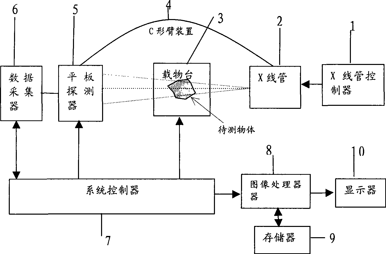

Image

  • Method and system of X ray image three-dimensional reconstruction
  • Method and system of X ray image three-dimensional reconstruction
  • Method and system of X ray image three-dimensional reconstruction

Examples


Embodiment 1

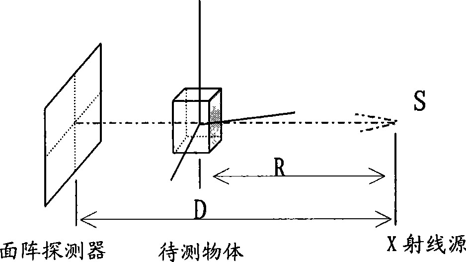
[0035] see figure 2 , first measure or calibrate the X-ray imaging system parameters D, R, d 0 . D is the distance between the X-ray source S and the area array detector, R is the distance between the X-ray source S and the rotation center axis of the object to be measured, d 0 is the pixel pitch of the area array detector (the supplier of the area array detector can provide this parameter).

[0036] see image 3 , to rotate the X-ray imaging system or the stage, so that the imaging system and the object on the stage undergo relative circular or helical motion, and perform image sampling. S is the X-ray tube, which moves along a circular track (sampling circle), and the track of the area array detector opposite to it is also a circle (in the case of a C-arm, the area array detector and the X-ray tube will be in the movement on the same sampling circle). The object to be measured is placed on the stage, the centerline SO of the X-ray cone ray beam passes through the centr...

Embodiment 2

[0050] see Figure 4 , S is the X-ray tube, which moves along a circular trajectory (sampling circle), and the trajectory of the area array detector opposite to it is also a circle (in the case of a C-arm, the area array detector and the X-ray tube will be moving on the same sampling circle). The object to be measured is placed on the stage, the centerline SO of the X-ray cone ray beam passes through the central axis of rotation and is perpendicular to the area array detector, intersecting i 0 , corresponding to the i-th projection image 0 Column of pixels, a non-central line L of the X-ray cone beam i Point i on the intersecting surface array detector corresponds to the i-th column of pixels in the projected image, and the angle between the ray Li and the central line SO is β i , the angle between the central line SO and the reference axis (X axis) is θ. A frame of image I(θ) is collected at every θ angle, and the collected image data is compressed and stored in computer ...


PUM


Abstract

The invention discloses a method for three-dimensional reconstruction of x-ray images and includes the following steps: (1) obtaining the parameters of an imaging system by means of measurement or calibration; (2) sampling projection images; (3) building image data indexes; (4) setting viewpoint parameters; (5) computing view line parameters; (6) indexing and searching image data; (7) processing images; (8) displaying images. The invention also discloses an x-ray three-dimensional reconstruction system. Though the method and the system for three-dimensional reconstruction of x-ray images provided in the invention adopt a low-cost two-dimension x-ray image pick-up device, a multi-perspective three-dimensional image of an object to be measured can be obtained; so that doctors can carry out complete observation and perform correct diagnosis and treatment.

Description

technical field [0001] The invention relates to medical image processing technology, in particular to a method and system for reconstructing a three-dimensional image of an object according to two-dimensional X-ray image data. Background technique [0002] X-ray imaging technology is widely used in medical diagnosis, industrial non-destructive testing and scientific research. The X-ray imaging technology used in medical diagnosis can be divided into two categories: two-dimensional and three-dimensional. Two-dimensional has X-ray film, CR and DR, and three-dimensional has CT. Among them, the X-ray film is to record the intensity of X-rays passing through the object (such as the human body) to form a latent image on the photosensitive film, and then obtain the image of the object through development and fixing. The X-ray film imaging process is long, and the images obtained are analog, which is not convenient for modern computer processing and communication transmission, and ...

Claims


Application Information

Patent Timeline
Patent Type & Authority Applications(China)
IPC IPC(8): A61B6/00G01N23/04G01T1/161G06T5/00
Inventor 王光学
Owner BEIJING NORMAL UNIV ZHUHAI
Why Eureka
Eureka Blog
Learn More